I personally wouldn't believe that kind of offset until I ran offset sensitivity analyses w/respect to the resistors and Q3/Q4/Q11/Q14. There's a lot of gain in your VAS to potentially move things sideways. The analysis would tell you what sort of resistor tolerance you need in order to get that kind of offset voltage.
Tests on the BJT match requirements could be done by putting a signal generator in series with their emitters.
Tests on the BJT match requirements could be done by putting a signal generator in series with their emitters.
I have done some simulations on a similar circuit with astonishing results.
The linearising diodes here made with T6 and T12 reduces the distortion about 100x in simulation.
In the real world word i would only expect more than 10x because we dont have identical transistors T4-T5 and T8-T12 even if we try to match them.
And for distortion cancellation it is also important that Id T3 = Id T5 and Is T14. And the same forT9, T11 and T13.
IOP1 means theoretical ideal OP.
Hi, @stigigemla
I haven't looked into the distortion of the input stage along. In my mind, the distortion from the output stage should dominate anyway.
Right, it makes sense that adding T6&T12 would help the lower the distortion. Based on your approach, this mod below might work even better. With this, T8 and T12 would have the same current.
I want all 3 to have the same DC current. When T9 conducts a little more T11 conducts a little less. And then T13 gets the same more.
When the signal goes to max they all work from 0 to double DC current. R12 leaves the current for T11 + T13 so it must give the double current = half the value.
Ideally T8 and T12 should have the same transfer caracter. That is possible to achieve if we paralell 2 transistors as T12.
When the signal goes to max they all work from 0 to double DC current. R12 leaves the current for T11 + T13 so it must give the double current = half the value.
Ideally T8 and T12 should have the same transfer caracter. That is possible to achieve if we paralell 2 transistors as T12.
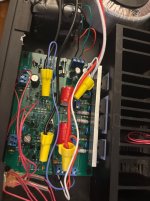
It is alive.
The supply is +-40V.
There are couple changes. As someone mentioned, the mismatch between input mosfets may cause issue. Right, this time I am not as lucky as my previous attempts. With same Vgs, I see more than 25% current mismatches. Thus, I swapped in trusty 2n5551/2n5401 as the input pairs. The Dc offset is within 10mV now. I also tried BC547/557 as input pairs. Guess what, they start to leak at 40V, although it is within specs on paper. They don’t work in the circuit at all.
Attachments
Last edited: