Ah realised I've been doing the calculations wrong.
The throat is the opening where the compression chamber connects to the horn right?
If that's the case, the formula would be:
fh = (c * S_throat) / (2 * pi * Vol_CC)
fh = (342m/s * 0.0035m^2) / (2 * 3.142 * 0.00154m^3)
fh = 123Hz
The throat is the opening where the compression chamber connects to the horn right?
If that's the case, the formula would be:
fh = (c * S_throat) / (2 * pi * Vol_CC)
fh = (342m/s * 0.0035m^2) / (2 * 3.142 * 0.00154m^3)
fh = 123Hz
I guess it's time for me to sleep, made a mistake in the previous calculation, resultant fh should be 1233Hz.
How bout this for a change?
Tapering the end to close, and making the horn port(mouth?) wider.
Based on the dimensions of 21" x 13" x 3"(deep)
fh = (342m/s * 0.00464m^2) / (2 * 3.142 * 0.00034^3) = 743Hz
hmmm, doesn't seem to work, any suggestions?
Argh... hate the calculations. Guess I will just make a prototype and listen from there.
Attachments
Ravener,
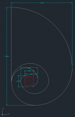
According to your drawing in post 1162, the compression chamber would be approximated by a circular chamber of 3.6 in in diam by 3 in deep = 0.50 liters. The throat area I am guessing is about 1.75 in across x 3 in deep = 34 cm^2. (You have a throat that goes to nowhere, which I mistakenly thought led to an output).
So fh = (342 m/s * 0.0034 m^2)/(6.284 * 0.0005 m^3) = 370 Hz.
370 Hz is a little on the high side and it means that lots of mid-range will come out of horns and cause phase delay problems with your ears and ruin spatial imaging. You can fix this by expanding the driver chamber volume by adding a sub chamber beneath the main horn connected with a hole, or add raised (hollow) suprabaffle above where you mount driver to boost volume. Alternatively, the easiest fix is to simply clamp down on the throat area by a factor of 0.75x - put a constrictor plate there (1.3 in wide gap). The horn expansion you have is good - it will result in quite a bit of gain in the bass notes. The mouth area/throat area looks approximately 10:1 - so not bad.
Last edited:
Good to hear, I will adjust accordingly and build using this then...
Time for me to get some sleep, hopefully I can wake up early enough to go source for materials, and hopefully they are as cheap here as in the states...
Time for me to get some sleep, hopefully I can wake up early enough to go source for materials, and hopefully they are as cheap here as in the states...
More foam-core wackiness: 😀
IG
An externally hosted image should be here but it was not working when we last tested it.
An externally hosted image should be here but it was not working when we last tested it.
An externally hosted image should be here but it was not working when we last tested it.
IG
IG,
You beat me to it. Nice work 🙂 I have been thinking about doing a front horn but in 8 segments and curving it. I have been looking at Tractrix profiles and such but haven't gotten to the point of cutting foam yet. I made a mock up in plain paper just to see if the segments bend and curve the way I intended.
How does it sound?
IG,
You beat me to it. Nice work 🙂 I have been thinking about doing a front horn but in 8 segments and curving it. I have been looking at Tractrix profiles and such but haven't gotten to the point of cutting foam yet. I made a mock up in plain paper just to see if the segments bend and curve the way I intended.
How does it sound?
Not too bad. The small BLH counters baffle-step pretty well and upper-bass is even hot enough on certain material that I wanted to try a small front horn to lift midrange a bit. I just threw it together with no calculations, came out ~40°, a bit too aggressive, did not have enough foamcore left to make a larger mouth. Gives ~6dB of gain from 400Hz to 4kHz, with some peaking on both ends of the BW. Also had to add a super-tweeter because it killed upper treble output.
IG
IG,
6 dB is not too bad. Too bad it impacts the high bandwidth. With properly designed curved horn, can that impact be reduced? Something like tractrix shape is used on HF correct?
6 dB is not too bad. Too bad it impacts the high bandwidth. With properly designed curved horn, can that impact be reduced? Something like tractrix shape is used on HF correct?
Hot day outside, just got home from shopping. Got myself some 5mm thick foam board, a glue gun, and gorilla glue to seal the top.
Shall rest a bit first and start after I had my dinner.
Shall rest a bit first and start after I had my dinner.
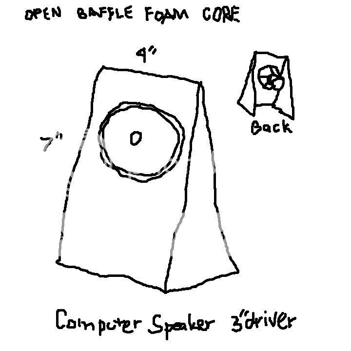
Foam core Open Baffle computer speaker.
Below is a rough sketch.
Is there an OB 3" driver that would work well in this?
Maybe bass down to 100-200hz?
Below is a rough sketch.
Is there an OB 3" driver that would work well in this?
Maybe bass down to 100-200hz?
An externally hosted image should be here but it was not working when we last tested it.
Hopefully the image appears...
Below is a rough sketch.
Is there an OB 3" driver that would work well in this?
Maybe bass down to 100-200hz?
Below is a rough sketch.
Is there an OB 3" driver that would work well in this?
Maybe bass down to 100-200hz?
Making$,
There is a deal on a 3 in full range driver with high Qts at Madisound for $2. Aurasound NS3 16 ohm neodymium driver I think. It would be perfect for this. I was going to get 50 then they are only $1. Cal has tried them in the Cornu and says they are pretty good. You may want to wire in parallel to get 8 ohms.
There is a deal on a 3 in full range driver with high Qts at Madisound for $2. Aurasound NS3 16 ohm neodymium driver I think. It would be perfect for this. I was going to get 50 then they are only $1. Cal has tried them in the Cornu and says they are pretty good. You may want to wire in parallel to get 8 ohms.
We are going to have to coin a new description of DIY foam board speaker builders. FOAMERS!
I just built my first one using the Dayton ND 105 four inch in a quarter wave design. It even impressed my wife with its rich bass.
I just built my first one using the Dayton ND 105 four inch in a quarter wave design. It even impressed my wife with its rich bass.
KLBird,
Congrats on the first build! please post pics!
Foamers Rule! Foaming at the mouth rabid that is 🙂
Congrats on the first build!
please post pics!Foamers Rule! Foaming at the mouth rabid that is 🙂
Last edited:
Making$,
Here is the link to the NS3 driver I was talking about. The FR curve actually looks pretty good.
The Madisound Speaker Store
Here is the link to the NS3 driver I was talking about. The FR curve actually looks pretty good.
The Madisound Speaker Store
IG,
6 dB is not too bad. Too bad it impacts the high bandwidth. With properly designed curved horn, can that impact be reduced? Something like tractrix shape is used on HF correct?
FF85WK does not have the motor strength or rising response to be behind such an aggressive horn. 90° would be better, maybe parabolic could be interesting, though much hard to to make. Tractrix does get more HF out from a compression driver, don't know how it would do for a cone driver. I should look up Bruce Edgar's old article that was for a 5" JLB midrange IIRC.
IG
I am gonna cut some tractrix panel tonight and glue them up. Should be fun. I don't have a clue how big to make it for a 3.5 in driver so I will just try something. Do you have a thread to point me to? I bet GM would know.
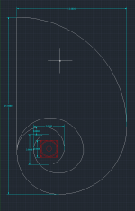
Tweaked the design a little, made the compression chamber rounder and the throat tighter.
fh = (342 x 0.00194m^2) / (2 * 3.142 * 0.00050m^3) = 210Hz
Seems rather reasonable...
Shall be starting work using this.
edit: upon looking at tractrix horns... mine seemed like an asymmetric curved tractrix...
fh = (342 x 0.00194m^2) / (2 * 3.142 * 0.00050m^3) = 210Hz
Seems rather reasonable...
Shall be starting work using this.
edit: upon looking at tractrix horns... mine seemed like an asymmetric curved tractrix...
Attachments
I am gonna cut some tractrix panel tonight and glue them up. Should be fun. I don't have a clue how big to make it for a 3.5 in driver so I will just try something. Do you have a thread to point me to? I bet GM would know.
You might glean some useful bits from the old Bruce Edgar article:
I ought to go through it again myself.
IG
- Home
- Loudspeakers
- Full Range
- Foam Core Board Speaker Enclosures?