That might work. You have the necessary RF test equipment, and experience in building radio systems? If not, start with an AM radio.
Obviously i have only very minimum experience and equipment. I did a straight through ZN414 and a BJT discrete superhet AM radio some 15 years ago but that's it. I'm gonna go ahead and do it, though. If it doesn't work, that's fine.. a few dollars and some hours of my life are wasted but that's it. A fair trade i'd say.
If all you want is a cheap tube tuner I'll add to the chorus of people suggesting the Dynaco FM-3. Lots of mods and upgrades available and sound quality that makes it worth the effort.
Hi..
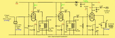
No IF-transformers are used to couple the stages. From there, it goes to a 6BN6-based limiter+quadrature detector to extract the audio signal which goes to power amp (or the LA3361 stereo decoder) and also fed back to the front end's AFC input.
So as you can see, basically i want to the place the LA1260 IC with tube-based circuit. Does this make sense? Will it work?
That won't work. You can do this with BJTs: amplify 10MHz+ with simple RC coupled gain stages since you can always drive up the gm enough to get useful voltage gain with passive collector loads of 100R or even 50R. It might take 50mA of collector current, though, and it has been done before.
VTs don't have enough gm to allow you to get the plate loads down far enough so capacitance won't be a problem. You're forced to use tuned LC loads that can incorporate device internal capacitance in their design.
You can't amplify 10MHz with grounded cathode triodes. You need pentodes or cascodes, with at least single-tuned IFTs or preferably double-tuned IFTs. Or possibly LTPs, which is what IF chips often use.
You can use grounded cathode triodes for 10MHz. However, you will have to neutralize them (PITA) and that's not user friendly since it's not "set and forget it". Pents and cascodes are better since this is typically a low level stage anyway, and you need the extra voltage gain that pents and cascodes can provide.
I predict intense frustration, together with wasting some minutes of our lives too as we try to help you. You will get nowhere unless you have an RF sig gen and the knowledge of how to use it. A 'scope may be needed too.ballpencil said:Obviously i have only very minimum experience and equipment. I did a straight through ZN414 and a BJT discrete superhet AM radio some 15 years ago but that's it. I'm gonna go ahead and do it, though. If it doesn't work, that's fine.. a few dollars and some hours of my life are wasted but that's it. A fair trade i'd say.
10MHz is about the point where details of layout begin to have a significant effect on RF circuits. Not as hard as VHF, but harder than medium wave AM. Forget all you have learnt about audio circuit layout; RF is different. You will either need a ground plane or a separate star ground for each stage. You will need to decouple the heater supply, and this is best done by grounding one side and adding caps to the other side.
Do a lot of reading on amateur radio websites - we are used to DIY RF.
Yes, of course, but I assumed that someone who wants to avoid IFTs would even more want to avoid neutralisation!Miles Prower said:You can use grounded cathode triodes for 10MHz.
I predict intense frustration, together with wasting some minutes of our lives too as we try to help you. You will get nowhere unless you have an RF sig gen and the knowledge of how to use it.
I have to at least try or will forever have that itch. I realize it will be challenging to say the least so i'm prepared for the worst and hence we can swap that "intense frustration" with "temporary disappointment". Good thing about online forums is that nobody are forced to help so hopefully no one would feel they wasted their time helping me.
I'll start by drawing schematic then the PCB and maybe this forum can help foresee future problems from the designs.
Perhaps we can start by scrutinizing the attached schematic? Would this work?
One question, the 100pF and RFC on the 6BN6 grid, can they be replaced by another 10MHz Ceramic filter and 1Meg grid leak resistor?
Another question is the 10.7MHz IFT. Part number 42IF123 from mouser has 25k primary impedance and 4k secondary. The plan is to connect both secondaries together to get a 25k:25k IFT (one end of the secondaries goes to GND while the other end connects to each other). Will it work? Parafeed connection as shown should also protect it from HV, correct?
Attachments
10.7MHz ceramic filters are usually designed to work into 330 ohms, not high impedance, so you will need a matching IFT for each. Wrong termination impedance means poor passband shape. Consult some datasheets.
Your 25k IFT is heavily loaded by the 5k6 anode resistor. This means low gain and maybe wider bandwidth than you need. If you must use parafeed, use a choke instead of a resistor.
Why are you dropping supply rail voltage with a zener? That will effectively amplify any error.
Your 25k IFT is heavily loaded by the 5k6 anode resistor. This means low gain and maybe wider bandwidth than you need. If you must use parafeed, use a choke instead of a resistor.
Why are you dropping supply rail voltage with a zener? That will effectively amplify any error.
10.7MHz ceramic filters are usually designed to work into 330 ohms, not high impedance, so you will need a matching IFT for each. Wrong termination impedance means poor passband shape. Consult some datasheets.
You're right, thank you. Left side of the Cerafil is ok since it's an existing front-end. Right side will be terminated to 330R grid leak resistor, instead of 1M. I hope this is OK although i would lose some gain compared to using IFT. I read from the datasheet that at 10.7MHz, terminating with IFT is not as necessary as at 455kHz (something about spurious counter-measuring).
Your 25k IFT is heavily loaded by the 5k6 anode resistor. This means low gain and maybe wider bandwidth than you need. If you must use parafeed, use a choke instead of a resistor.
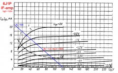
I was thinking the other way around, see attached loadline. I thought by having 25K IFT, i won't be loading the tube too much (the only load it sees is approximately the anode resistor since 25k>>5k6. Perhaps since the voltage swing is very small, i don't have to worry?
Since we are discussing about gain, is there any typical value for gain requirement from the IF strip? I'm questioning my decision of using only two pentode gain stage. As shown with the 5k6 anode load, the gain is about 30dB per stage (30V/V). So two stages as shown yields 60dB. Is this enough? I read that it's a good practice not to go over 60dB of gain on one frequency band. Or i still need to go choke loaded parafeed as shown?
Why are you dropping supply rail voltage with a zener? That will effectively amplify any error.
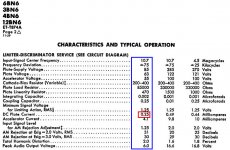
I thought it would be better than a simple resistor since the current is only 0.25mA. Dropping 35V on a resistor flowing 0.25mA translates to 140k. I don't know, this seems rather unusually too large value for me. Basically i need +85v as the plate supply voltage since i'm following the recommended values found on the 6BN6 datasheet. What is best to achieve this?
Attachments
Last edited:
From Sturley - Radio Receiver Design, 1945
An externally hosted image should be here but it was not working when we last tested it.
You have a helluva long way to go before attempting this, I'm afraid.
This is just plain wrong. While it's possible, and even desirable, to operate gain stages with low plate currents into large load resistances, that doesn't apply to IF gain stages, whether these are hollow state or solid state. You want to maximize gain, and that means running IF amp devices hot, both figuratively and literally. You need more than 50V, and you need a heavier current to get that gm up. When working on TVs and radios, you no more want to grab an IF tube than a power tube because these will be getting just as hot.
You're not worried about harmonic distortion since you get rid of it with LC tuners and.or BPFs. Don't bother with parafeed here, unless you're using IFTs with ferrite cores, and at 10MHz, these can just as easily be air coils that don't have that saturation problem anyway.
I thought it would be better than a simple resistor since the current is only 0.25mA. Dropping 35V on a resistor flowing 0.25mA translates to 140k. I don't know, this seems rather unusually too large value for me. Basically i need +85v as the plate supply voltage since i'm following the recommended values found on the 6BN6 datasheet. What is best to achieve this?
This is just plain wrong. While it's possible, and even desirable, to operate gain stages with low plate currents into large load resistances, that doesn't apply to IF gain stages, whether these are hollow state or solid state. You want to maximize gain, and that means running IF amp devices hot, both figuratively and literally. You need more than 50V, and you need a heavier current to get that gm up. When working on TVs and radios, you no more want to grab an IF tube than a power tube because these will be getting just as hot.
You're not worried about harmonic distortion since you get rid of it with LC tuners and.or BPFs. Don't bother with parafeed here, unless you're using IFTs with ferrite cores, and at 10MHz, these can just as easily be air coils that don't have that saturation problem anyway.
While it's possible, and even desirable, to operate gain stages with low plate currents into large load resistances, that doesn't apply to IF gain stages, whether these are hollow state or solid state. You want to maximize gain, and that means running IF amp devices hot, both figuratively and literally. You need more than 50V,
But the 6BN6 tube that are getting low 85v supply voltage is not even an IF gain stage.. 😕 It's the quadrature detector and i'm merely following the datasheet as attached.
I also attach the revised load line of using choke loaded parafeed going to a 25k IFT. Gain is around 100V/V or 40dB. Two 6J1P stages would then give 80dB of IF stage gain. Perhaps this would be lower when operating at 10.7MHz?
Attachments

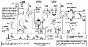
Found this valuable info from turneraudio. Pretty much basically what i'm trying to do: 2 stage pentode IF amp + FM demodulator except:
- It's using Ratio Detector, not Quadrature.
- Higher HT supply of 170V instead of 120V like mine. With the way G2 is wired i'm guestimating this translates to around 10mA of plate current, compared to 8.5mA from mine.
- AGC
- Transformer-loaded vs parafeed
- It's using Ratio Detector, not Quadrature.
- Higher HT supply of 170V instead of 120V like mine. With the way G2 is wired i'm guestimating this translates to around 10mA of plate current, compared to 8.5mA from mine.
- AGC
- Transformer-loaded vs parafeed
Attachments
Don't forget that a critically-coupled double-tuned IFT will present half the dynamic impedance of each coil to the anode, so stage gain will be half what you expect.
The 6J1P appears to be equivalent to 6AK5/EF95. This was intended for VHF/UHF front ends or 45MHz IF strips. At 10.7MHz you may find it 'lively' i.e. prone to parasitic oscillation. Better to use something with a lower grid input conductance. Whether you need AGC is debateable.
The 6J1P appears to be equivalent to 6AK5/EF95. This was intended for VHF/UHF front ends or 45MHz IF strips. At 10.7MHz you may find it 'lively' i.e. prone to parasitic oscillation. Better to use something with a lower grid input conductance. Whether you need AGC is debateable.
Would 6BD6 be a better choice? The turner audio schematic above shows 6BA6 as 10.7MHz IF amplifier. 6BD6 has lower input capacitance (4.3 vs 5.5pF) and lower Gm 2350 vs 4300 at the same supply voltages.
Hello ,
new project but only in german language :
UKW-Empfang mit Batterieröhren von Thomas Moppert & Ernst Rößler
Kind regards , Alexander .
new project but only in german language :
UKW-Empfang mit Batterieröhren von Thomas Moppert & Ernst Rößler
Kind regards , Alexander .
For 10.7MHz IF you need reasonably high gm and low grid-anode capacitance. Input capacitance does not matter as you tune it out with the IFT. In Europe the two popular valves for this purpose were EF85 and EF89. In the US probably 6BA6 then 6BJ6, or 6AU6 if no AGC used.ballpencil said:Would 6BD6 be a better choice? The turner audio schematic above shows 6BA6 as 10.7MHz IF amplifier. 6BD6 has lower input capacitance (4.3 vs 5.5pF) and lower Gm 2350 vs 4300 at the same supply voltages.
Hello ,
new project but only in german language :
UKW-Empfang mit Batterieröhren von Thomas Moppert & Ernst Rößler
Kind regards , Alexander .
😀
https://translate.google.co.uk/translate?sl=auto&tl=en&js=y&prev=_t&hl=en&ie=UTF-8&u=http%3A%2F%2Fwww.jogis-roehrenbude.de%2FLeserbriefe%2FRoessler_Moppert-Batterieroehren-Superhet%2FBatterieroehren_UKW-Superhet.htm&edit-text=
Regards
M. Gregg
Hi,
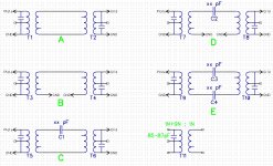
For this FM receiver project, as mentioned previously, my plan is to use IF transformers that were meant for use in low voltage solid state circuit.
The IF transformer i'm using has 10 wounds in primary with tap after 9 wounds (so 9+1). Primary is paralleled with around 85-87pF of capacitor. Secondary is 1 wound.
The plan is to connect the secondary back-to-back and parafeed the transformers from the earlier stage and connect the other end to the valve grid of the following stage.
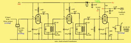
I have difficulty in determining the best way to connect the secondaries. As shown in the attachment, there are five ways to do it. Which would be the best way? Also, what value of coupling cap if either option C, D or E is the best way?
For this FM receiver project, as mentioned previously, my plan is to use IF transformers that were meant for use in low voltage solid state circuit.
The IF transformer i'm using has 10 wounds in primary with tap after 9 wounds (so 9+1). Primary is paralleled with around 85-87pF of capacitor. Secondary is 1 wound.
The plan is to connect the secondary back-to-back and parafeed the transformers from the earlier stage and connect the other end to the valve grid of the following stage.
I have difficulty in determining the best way to connect the secondaries. As shown in the attachment, there are five ways to do it. Which would be the best way? Also, what value of coupling cap if either option C, D or E is the best way?
Attachments
I would use C or D. The cap to use depends on how much coupling you need. Experiment is the only way to find out. You need to try various values and measure the response. I would guess something in the range from 100pF up to a few nF is worth exploring, but it depends on the tuned circuit loaded Q and how tight is the coupling of the secondary.
- Status
- Not open for further replies.
- Home
- Amplifiers
- Tubes / Valves
- FM Tube radio design