Hi there,
Has anybody any infor on FM Acoustics amplifiers or pre.
Very interested in their technologies. Schematic will be even
better.
Greatly appreciated.
Has anybody any infor on FM Acoustics amplifiers or pre.
Very interested in their technologies. Schematic will be even
better.
Greatly appreciated.
regarded this brand I have start this thread:
http://www.diyaudio.com/forums/soli...amplifier-absolute-state-art.html#post1963472
http://www.diyaudio.com/forums/soli...amplifier-absolute-state-art.html#post1963472
If you read through their website, you will see that they do extensive matching, measuring testing to their equipment before they are sold.
Besides they make their own transistors(!), and I especially like their look upon powersupplies - uF is not important, series resistance is!
I guess you can call it like a swiss clock manufacturer.
A schemaitc will give you an idea of the topology, but many of the above mentioned details are the reason for the high price, and rightly so.
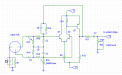
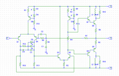
I once did some reverse engineering from some pictures - it might have errors, but check it out:
Besides they make their own transistors(!), and I especially like their look upon powersupplies - uF is not important, series resistance is!
I guess you can call it like a swiss clock manufacturer.
A schemaitc will give you an idea of the topology, but many of the above mentioned details are the reason for the high price, and rightly so.
I once did some reverse engineering from some pictures - it might have errors, but check it out:
Attachments
If you read through their website, you will see that they do extensive matching, measuring testing to their equipment before they are sold.
Besides they make their own transistors(!), and I especially like their look upon powersupplies - uF is not important, series resistance is!
I guess you can call it like a swiss clock manufacturer.
A schemaitc will give you an idea of the topology, but many of the above mentioned details are the reason for the high price, and rightly so.
I once did some reverse engineering from some pictures - it might have errors, but check it out:
unbelievably unlikely that they own a silicon foundry... almost zip.
_-_-bear
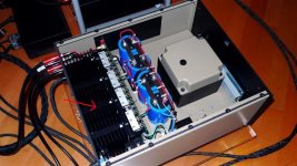
ask there:Can anyone identify this heatsink, model and manufacturer?
The T-profiles are mounted in a slot in the heatsink.
Thanks
Home - Fischerelektronik
I have been looking at this design. FM acoustics uses two unusual diodes in the ccs. The color rings are orange, brown and yellow = 314 = 1N314. This is an gold diffusion germanium diode made by BKC International. What is the purpose of using this diode?
The other diodes are 1N4148 used in an other position.
The other diodes are 1N4148 used in an other position.
Attachments

unbelievably unlikely that they own a silicon foundry... almost zip.
_-_-bear
At those pricese Huber could ....🙂
I have been looking at this design. FM acoustics uses two unusual diodes in the ccs. The color rings are orange, brown and yellow = 314 = 1N314. This is an gold diffusion germanium diode made by BKC International. What is the purpose of using this diode?
The other diodes are 1N4148 used in an other position.
They had a carton full?
Are they Zeners?
What are the specs?
Perhaps they handle more current than the usual 1N4148 or 1N914?
Maybe they look pretty?
Or are they there to confuse people? 😀
Oh wait, germanium? Different Vdrop.
_-_-bear
At those pricese Huber could ....🙂
Why build your own, when there are companys like Semefab Semiconductor Manufacturing, MEMS Foundry, MOS, Bipolar
diodes on FM Acoustic
These ring colored diodes are in fact old Philips BA314, called "stabistors", only plain silicon diodes with a very defined drop, used 30 years ago for more previsible polarization of transistor class B output and constant current sources (like FM Acoustics), without need of trimming.
Hope this help.
regards,
Marcos
Those schematics look very ''English'' concepts to me. Do they have a secret UK designer engineer or something?
concerning BA314 you are right - go toThese ring colored diodes are in fact old Philips BA314, called "stabistors", only plain silicon diodes with a very defined drop, used 30 years ago for more previsible polarization of transistor class B output and constant current sources (like FM Acoustics), without need of trimming.
Hope this help.
regards,
Marcos
BA314 pdf, BA314 description, BA314 datasheets, BA314 view ::: ALLDATASHEET :::
this diode is a low forward voltage drop and low noise diode - go toI have been looking at this design. FM acoustics uses two unusual diodes in the ccs. The color rings are orange, brown and yellow = 314 = 1N314. This is an gold diffusion germanium diode made by BKC International. What is the purpose of using this diode?
The other diodes are 1N4148 used in an other position.
http://pdf1.alldatasheet.com/datasheet-pdf/view/155394/ETC1/1N314.html
as I know, such diodes are often to find as anti saturation diodes (shorting the recovery time in case of clipping).
Where this diodes exact located in the CCS?
Last edited:
tiefbassuebertr,
Forget about the 1N314, it is a BA314 diode.
It is used in the ccs.
I found a much better data sheet where the color rings is described.
Forget about the 1N314, it is a BA314 diode.
It is used in the ccs.
I found a much better data sheet where the color rings is described.
Attachments
Last edited:
Take a look at the ouput stage diagram in post 4, why is there en 10uH coil in the collector, and what size is the resistors R15 and R6?
Take a look at the ouput stage diagram in post 4, why is there en 10uH coil in the collector, and what size is the resistors R15 and R6?
At LF the connection is DC to the outputs, but at HF it rises, so the connection is through the resistor. At HF is where you have problems with weird loads and parasitics... this effectively limits the current that can be drawn above some frequency where the choke starts to look like a highish impedance.
It's sort of like the output choke found in many solid state amps in series with the load.
_-_-bear
- Status
- Not open for further replies.
- Home
- Amplifiers
- Solid State
- fm acoustics