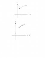
Maybe we are not talking about the same thing. I hope this makes sense. Pardon my calligraphy.
Your drawing is clear and coincides with all the other renderings I have seen of the BH curves of ferrite. Of course you only show one side of the minor loop which would also form a small hysteresis loop.
I believe are are talking about the same thing but I am somewhat dumbfounded that I have to argue that it is a hysteresis effect (exactly as you have just drawn).
Maybe as a middle ground we can agree that hysteresis requires nonlinearity (nonlinearity does not require hysteresis) and when I say hysteresis you can just think "nonlinearity".
Okay?
David
Why would it form a small hysteresis loop?Of course you only show one side of the minor loop which would also form a small hysteresis loop.
If you want to know the distortion/intermodulation of a motor why don´t you clamp the coil and simply measure it 🙄
Btw that Scan 8640 motor style is outdated and far from optimum .
For optimizing motors there is a new FEA software called MoTIV , the evaluation version is heavily restricted but you can see which motor topology is an improvement .
http://www.dyneanalytics.com/product-1.htm
Btw that Scan 8640 motor style is outdated and far from optimum .
For optimizing motors there is a new FEA software called MoTIV , the evaluation version is heavily restricted but you can see which motor topology is an improvement .
http://www.dyneanalytics.com/product-1.htm
An externally hosted image should be here but it was not working when we last tested it.
Why would it form a small hysteresis loop?
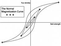
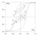
Why wouldn't it? Hysteresis just means there is a different curve "going up" than "going down". The graphs you normally see start at the center and swing through a broad region from saturation to saturation (hyst 1 attached) but you can swing H any amount and the characteristics will always swing aroung a minor hysteresis loop. (Hyst 2 and hyst 3).
For those that haven't seen these curves before these are the basic curves of a magnetic material. H is the magnetizing force that you apply, B is the magnetizing flux that remains. The curves flatten top and bottom as a form of saturation. You can apply more H but B won't go any higher. Hysteresis means that the B drags behind as you reverse direction of H, and that is a good thing: without it a magnet woudn't be a magnet. The B point on the return where H is 0 (where the central y axis intersects the curve top middle) shows the remnance after saturation (magnetization).
This also shows how it is hard to demagnetize something. Letting H go to zero leaves the material magnetized (B non 0). You could swing H to some particular negative value, but it is hard to predict precisely what value would be required. In the end, swinging it back and forth in ever diminishing amounts will have it loop around the 4 quadrants (in a minor hystersis loop) until it converges on 0 for B, i.e. demagnetized.
David S.
Attachments
Gander's paper gives good curves on various distortion effects.
http://www.aes.org/tmpFiles/elib/20111028/3936.pdf
Page 22 and 23 goes into the flux ring 2nd harmonic reduction.
David S.
http://www.aes.org/tmpFiles/elib/20111028/3936.pdf
Page 22 and 23 goes into the flux ring 2nd harmonic reduction.
David S.
Well, would you say that a Kms(x) curve exhibits hysteretical behaviour? No, you would probably say that it's merely a function which is not linear. But there's really no difference between the way Kms(x) and B(H) behave, either, since both are just simple non-linear functions as far as the driver is concerned. In order to "jump" onto a different part of the hysteresis loop, H needs to significantly reverse (go negative all the way to the other side), and such a phenomenon, as far as I know, cannot happen with a regular driver with regular input power.Why wouldn't it? Hysteresis just means there is a different curve "going up" than "going down". The graphs you normally see start at the center and swing through a broad region from saturation to saturation (hyst 1 attached) but you can swing H any amount and the characteristics will always swing aroung a minor hysteresis loop. (Hyst 2 and hyst 3).
For those that haven't seen these curves before these are the basic curves of a magnetic material. H is the magnetizing force that you apply, B is the magnetizing flux that remains. The curves flatten top and bottom as a form of saturation. You can apply more H but B won't go any higher. Hysteresis means that the B drags behind as you reverse direction of H, and that is a good thing: without it a magnet woudn't be a magnet. The B point on the return where H is 0 (where the central y axis intersects the curve top middle) shows the remnance after saturation (magnetization).
This also shows how it is hard to demagnetize something. Letting H go to zero leaves the material magnetized (B non 0). You could swing H to some particular negative value, but it is hard to predict precisely what value would be required. In the end, swinging it back and forth in ever diminishing amounts will have it loop around the 4 quadrants (in a minor hystersis loop) until it converges on 0 for B, i.e. demagnetized.
David S.
Well, would you say that a Kms(x) curve exhibits hysteretical behaviour? No, you would probably say that it's merely a function which is not linear. But there's really no difference between the way Kms(x) and B(H) behave, either, since both are just simple non-linear functions as far as the driver is concerned. In order to "jump" onto a different part of the hysteresis loop, H needs to significantly reverse (go negative all the way to the other side), and such a phenomenon, as far as I know, cannot happen with a regular driver with regular input power.
Sorry but you totally misunderstand what hysteresis means. Any physical phenomonon that has a component that "lags behind" will have a different characteristic curve going in one direction than going in the other. It doesn't retrace its steps but always inscribes a loop when driven in alternate directions. It may be clearest to see, if you trace BH curve of magnetic material, by pushing from full saturation one direction to full saturation the other direction, but this is not required and there will always be an enclosed loop of some area no matter how small the excursion. (This was illustrated by a couple of the drawings above. They showed minor as well as major loops.)
As I said you can have nonlinearity without hysteresis but you can't have hysteresis without nonlinearity. Perhaps, in the case of magnetic material, it is the nonlinearity that matters, but it comes from the hysteresis of the material and the hysteresis is always there (for major and minor loops).
Finally, woofer suspensions usually have significant "creep" phenomenon, so they would exhibit hysteresis as well.
David S.

Gander's paper gives good curves on various distortion effects.
http://www.aes.org/tmpFiles/elib/20111028/3936.pdf
Page 22 and 23 goes into the flux ring 2nd harmonic reduction.
David S.
This is how I always understood the action of shorting rings placed around the pole piece, to counteract the flux modulation due to the ac field generated by current in the VC. This modulation creates 2nd harmonic distortion.
But, most of the discussion in this thread has been about 3rd harmonic distortion, also caused by current in the VC.
On page 14 of the paper it is mentioned:
"The presence of conductive rings directly within the gap may also tend to reduce third-harmonic distortion generated due to the magnetization of the magnetic gap pole surfaces by the voice-coil flux."
So, if I am understanding the paper correctly:
- the 2nd harmonic is generate by modulation of the overall flux in the (magnet + plates + pole piece) circuit, resulting in increasing/decreasing the flux in the gap depending on the polarity of the current thru the VC....hence 2nd harmonic
- the 3rd harmonic is generated by "small scale" magnetization of the pole and plate surfaces local to the VC. Since 3rd harmonic, the effect is to compress the peaks of the waveform no matter what the polarity of the current thru the VC.
Is this correct?
Have I drawn correctly what you are saying? My vision is above, yours below.Sorry but you totally misunderstand what hysteresis means. Any physical phenomonon that has a component that "lags behind" will have a different characteristic curve going in one direction than going in the other. It doesn't retrace its steps but always inscribes a loop when driven in alternate directions. It may be clearest to see, if you trace BH curve of magnetic material, by pushing from full saturation one direction to full saturation the other direction, but this is not required and there will always be an enclosed loop of some area no matter how small the excursion. (This was illustrated by a couple of the drawings above. They showed minor as well as major loops.)
As I said you can have nonlinearity without hysteresis but you can't have hysteresis without nonlinearity. Perhaps, in the case of magnetic material, it is the nonlinearity that matters, but it comes from the hysteresis of the material and the hysteresis is always there (for major and minor loops).
Finally, woofer suspensions usually have significant "creep" phenomenon, so they would exhibit hysteresis as well.
David S.
Attachments
I've had similar debates with people over the hysteresis loops of magnetic materials as applied to cored inductors in passive networks - there seems to be a pervasive belief/myth among many that cored inductors only produce non-linear distortion at (and nearly approaching) saturation, and that as long as you spec the right core size/material and numbers of turns so that you're well away from saturation at anticipated maximum drive levels a cored inductor is perfectly "fine", and doesn't produce distortion.It may be clearest to see, if you trace BH curve of magnetic material, by pushing from full saturation one direction to full saturation the other direction, but this is not required and there will always be an enclosed loop of some area no matter how small the excursion. (This was illustrated by a couple of the drawings above. They showed minor as well as major loops.)
As I said you can have nonlinearity without hysteresis but you can't have hysteresis without nonlinearity. Perhaps, in the case of magnetic material, it is the nonlinearity that matters, but it comes from the hysteresis of the material and the hysteresis is always there (for major and minor loops).
But unless I misunderstand something fundamental, all practical magnetic core materials used in cored inductors have hysteresis loops, at all drive levels, including levels that are well below saturation. (The "minor" loops in your diagram)
Now its true that saturation will produce a gross amount of distortion compared to that at low levels, and that the size of the minor loops may be quite small if the core material is well chosen, but they are still present and if they are present non-linear distortion must also be present, however small it might be.
It's also true that with a really good core material the level of distortion at non-saturated levels could in fact be quite a bit lower than the distortion of the driver it is feeding, however we have to keep in mind that distortion products are cumulative - a slightly lower level of distortion from an inductor is not necessarily masked by the slightly higher distortion of a driver, especially if they are of different orders.
We also have to keep in mind that as advances are made in the design of drivers that help to reduce distortion (such as those discussed in this thread that help reduce inductance and flux modulation) driver distortion in the midrange in particular could fall to the point where inductor distortion becomes a lot more significant than it is with poor drivers. (What is the bottleneck in performance today may not be tomorrow as technology advances...)
It baffles me that in many conversations I've had, so many people try to deny the existence of non-saturation related distortion in cored inductors, despite the fact that it can be readily measured, and can't seem to see the fundamental distinction between air cored inductors which introduce zero distortion at all power levels and cored inductors that produce at least some distortion at all power levels, however small it may be.
If some distortion is produced it needs to be measured and evaluated in the context of the overall design, not ignored as if it doesn't exist. I'm not saying that cored inductors are evil - often there is no choice but to use them for large values, but their distortion should be one of the parameters being considered and measured, and if its easy to use an air cored inductor for a certain coil without too much trouble or size, then do so.
Or am I just paranoid, and thinking about things that other people just don't worry about ? 😉
Last edited:
Is this correct?
No, it is not correct. It is a gross over simplification of what is really going on. In the motor structure we have magnetic fields that are nonlinear with displacement and current. Second and third harmonics are simply symptoms of this nonlinearity. The nonlinearities are complex and can generate all orders of harmonics depending on a large number of factors. It it were only second and third harmonics that were generated I don't think anyone would care, I wouldn't. Yes, at lower levels the dominate nonlinearites are second and third, but as the nonlinearities get "sharper" higher harmonics are generated and these are far more audible.
Mandrake
Steel has almost no hysteresis. Its PM materials that we are talking about becausethey have much higher levels of hysteresis than steel. Steel hysteresisis is insignificant even when close to saturation.
I think this whole discussion is confusing saturation and nonlinear B-H curves with hysteresis effects and until this difference is sorted out these arguments will continue to no point.
No, it is not correct. It is a gross over simplification of what is really going on.
I kinda figured as much.
Is there some literature on the topic you could point me to that would cover the topic in detail?
A bit of web searching did not turn up anything that appeared to go into any more depth.
I kinda figured as much.
Is there some literature on the topic you could point me to that would cover the topic in detail?
A bit of web searching did not turn up anything that appeared to go into any more depth.
I don't think you drawing was far off. I just wanted to make the point that hysteresis exists at any level and doesn't require swings with full saturation. This would give some area to a loop of any level.
To your question, the basic properties of materials are generally well explained such as in the Rob G reference:
Hysteresis in magnetic materials
Also the measurable attributes of a full woofer are well documented.
http://www.aes.org/tmpFiles/elib/20111028/3936.pdf
Not so clearly explained is the link between the individual elements and the end result. In general the various attributes have their effect at different frequency bands or levels, so they can be viewed somewhat in issolation. The flux modulation issue that the thread first discussed is in my understanding really just a 3rd harmonic distortion midrange effect. This is just a practical observation in that the "flux rings" that manufacturers add and the current drive tests I've made primarily changed 3rd harmonic level. At low frequencies it may be present but the excursion related nonlinearities far outweigh it. High impedance at resonance would also diminish it.
See if you can find any Klippel writings as he goes heavily into the various elements that make up woofer distortion.
For Simon, certainly any nonlinearities present in a system have to cast an effect over a signal of any level. If a system has a single nonlinear transfer curve then it can be described by the power series that makes that curve. The interesting part is how the contribution of each distortion order grows in level with increasing input in proportion to its order. So 2nd harmonic grows at a slow rate, as signal increases, and 10th at a proportionally higher rate. If a coil's core has 3rd 5th and 7th order nonlinearity, the 5th and 7th may (virtually) vanish below saturation, and the third fairly quickly as well, but they really must always diminish at a finite slope.
I remember measuring a spyder transfer function once. It was very smooth with a linear middle section and then a rounded transition to a steep second slope. We guessed its nonlinearity was primarily 3rd with maybe some 5th. We found a program that would fit a transfer curve to it and were surprised that we couldn't get even close to the shape until we included terms to 9th order. So even in the middle flat section it would have to contain some trace of 9th harmonic distortion.
Regards,
David
See if you can find any Klippel writings as he goes heavily into the various elements that make up woofer distortion.
Thanks! will give this paper a read...
http://www.klippel.de/uploads/media/Loudspeaker_Nonlinearities–Causes_Parameters_Symptoms_06.pdf
Thanks! will give this paper a read...
http://www.klippel.de/uploads/media/Loudspeaker_Nonlinearities–Causes_Parameters_Symptoms_06.pdf
Wow, that looks like an excellent one...covers everything.
David
Please see Figure 8 on page 12.Wow, that looks like an excellent one...covers everything.
David
Is this in line with your perspective on flux modulation?
Noteworthy is the complete lack of discussion of hysteresis as a magnetic effect although the saturation effect is discussed. Klippel does mention hysteresis as a mechanical effect so he does understand it.
I kinda figured as much.
Is there some literature on the topic you could point me to that would cover the topic in detail?
A bit of web searching did not turn up anything that appeared to go into any more depth.
There is literature on nonlinear systems, most noteworthey is Schetzen "Theories of Nonlinear Sytems", which is now back in print after being unavailable for a long time. But beyond Klippel there isn't much on loudspeakers. I would attribute this to the fact that nonlinear effects in loudspeakers are mostly nonaudible so the interest level in understanding them is fairly low.
I studied Nonlinear systems quite extensively while working with B&C, but then when we did the studies (trying to rank order the effects subjectively)that showed that the nonlinear effects were not actually audible I kind of lost interest.
This all pointed me in other directions for real life audible problems that do make a difference so that's where I spent my time.
Please see Figure 8 on page 12.
Is this in line with your perspective on flux modulation?
That section through page 14 covers the "flux modulation" subject. Note that he talks about Le(x) and Le(i). The Le(x) term is primarily related to the inductance and how it changes with low and high VC positions. Simple magnet structures put a lot more iron within the voice coil for inward displacement, driving inductance up. The copper caps and silver and copper plating in the vicintiy of the coil are the typical cures for this. The disease you are curing is modulation of HF impedance, but for the most part designers want to reduce inductance to extend bandwidth primarily for full range units. I also think that the high rising inductance creates a solenoidal force that can cause DC offset with large bass signals.
Le(i) is more the distortion causing "flux modulation" parameter that we are familiar with. It is the cause of the relatively cnstant 3rd harmonic midrange distortion. Rather than rings under the voice coil this is usually tackled with larger aluminum rings further back around the core pole (a ring that size under the voice coil would dramtically reduce sensitivity). This distortion stems from the nonlinearity of the magnetic material and is especially bad in ferrite.
Klippel describes it much the same but the particular figure isn't exactly analogous. His curve shows a typical BH nonlinearity but it is a one sided curve not showing the hysteresis we know would be there (he describes the hysteresis in the text). Also, I know the effect is largely 3rd harmonic yet he shows a largely 2nd order nonlinearity.
Both Klippels paper, the Gander paper and my descriptions are consistant in describing the distortion usually termed as "flux modulation" distortion.
David S
- Status
- Not open for further replies.
- Home
- Loudspeakers
- Multi-Way
- Flux modulation