Hi all,
I am working again over average current mode control with half bridge. And I am surprised again from unbalanced currents in the output. I start reading again and I found confuse in this two well known papers:
Unitrode slup083
The Stability Problem of the Half Bridge Topology
Using Current Mode Control (Refer to Figure 3)
Assume that 02 closes with a longer pulse width than 01.
Current mode control keeps the peak current equal, so the
amount of charge transferred from C2 is more when 02 is
closed. As a result the voltage at node 2 will decrease. The
next time 02 closes the voltage across the primary will be
less so the current ramp will have a slower slope. The peak
current will be kept the same, so the pulse width will be
wider: This means that the node 2 voltage decreases even
further; and eventually reaches zero. It is this stability problem
that has prevented the widespread use of the halfbridge
topology with current mode control. Fortunately
there is a simple solution to this problem, using an auxiliary
transformer winding made of small diameter wire with the
same number of turns as the primary winding, and two
small high voltage diodes. The credit belongs to an
unknown engineer who attended one of our seminars in
1984.
Abraham L Pressman smps design
5.4.2 Elimination of flux imbalance
Consider the waveform Vi in Fig. 5.3. It is taken off the top of the
current-sensing resistor and is hence proportional to power transistor
currents. The-on time ends when the peak of the ramp in Vi equals the
output voltage orthe error amplifier V eao' It can be seen in Fig. 5.3
that peak currents on alternate half cycles cannot be unequal as in
Fig. 2.4b and 2.4c because the error-amplifier output V eao is pretty
much a straight line and cannot change within one cycle because of its
limited bandwidth.
If the transformer core got slightly off center and started walking
up into saturation on one side, the voltage Vi would go slightly concave
upward close to the end of that on time. It would then equal Veao
earlier in time and terminate that on time sooner. Flux increase in
that half cycle would then cease, and in the next half cycle, since the
opposite transistor does not have a foreshortened on time, the core
would be brought back down in flux and away from saturation.
Since the peak of the voltage ramps in Fig. 5.3 (V) are equal, peak currents
on alternate half cycles must be equal. Thus flux imbalance and
the inequality of alternate currents shown in Fig. 2.4b is not possible.
Attachments
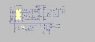
There is another way of doing it and that is to set up a voltage divider to give half voltage and use that as a reference signal to test the half bridge centre voltage the error can then be used to alter the set point of the current comparators. The schematic is too small to read.
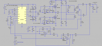
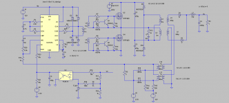
I’m sorry, its very small indeed. This is a bigger and worked variant. It works even without the additional winding and without series cap. But when I try to measure currents with current transformers then after a while the circuit start behaving like pure “one transistor forward”!
Attachments
I was expecting to see current sense resistors on the drains of the switching devices.
Using transformers to sense current in a system with possible DC can be a problem, saturation of the CT core is one problem the other is saturation of the main transformer core reducing the coupling to the current sense winding (secondary I believe in this case). Using current transformers designed to handle some DC might improve things. This type of CT is common in AC variable speed drives but they are often quite large. A hall effect current sensor might be an option as well.
I have not looked at the AN or data sheet for the control chip so I might not fully understand your circuit.
CTs handling pulsed DC are quite typical in SMPS, and they do a fine job. A diode is used on the secondary, so the burden resistance is effectively very high in the reverse direction, allowing magnetic reset.
Anyway, flux walking with a coupling capacitor doesn't happen. You're fine. There's no good way to control it on an SG3525, anyway -- you aren't given a differential balance, you'd have to inject charge into the timing capacitor every other cycle, and you don't know which cycles those are until it happens.
Tim
- Status
- Not open for further replies.
- Home
- Amplifiers
- Power Supplies
- flux again