Thanks - i will order a 100k attenuator today. how do i tell if i have a Williamson on non williamson version..? Which in your opinion is better..? Non Williamson.. will post some pics of my app today..
Waffly answer here, it depends on which topology was more competently designed.. LOL
The best way to figure out what yours is is to do some circuit tracing. I was somewhat surprised to find out mine is a Williamson as the schematic that seemed to be associated with it appeared to be inspired by the Mullard 5-20 design.
The best way to figure out what yours is is to do some circuit tracing. I was somewhat surprised to find out mine is a Williamson as the schematic that seemed to be associated with it appeared to be inspired by the Mullard 5-20 design.
[AHi kevinkr and Einric
Good news everybody - The NOS 829Bs have arrived - i will fit and bias them tomorrow.
Good news kevinkr - the 100k pot has arrived and i fitted it today (pic 5). I attach some photos of the inside - i think mine is an older model - my earth goes to a nut on the chassis via the negative pins (see my finger pointing at it - pic 4)
As you see i have replaced the filter caps with mundorf fancy things (pic 1 and 5) - not sure i can hear a benefit - maybe they are round the wrong way.
Also, the soldering inside (mine included) is lousy and messy (pic 3)- should i worry about that?
Finally i added cathode resistors to ground as per someones suggestion (pic 2) - makes biasing somewhat easier..
SO how old is this? Is it williamson..? do i have a dud Audioromy? will it sound even better with the new Pot and new Tubes ? - i guess we will find out tomorrow!
I think the schematic you are looking for is the one presented in this post:
http://www.diyaudio.com/forums/tube...atest-model-828a-mini-review.html#post3898892
More here: Audioromy FU29 828 | Audiokarma Home Audio Stereo Discussion Forums in particular see posts #7 and #8
And finally: http://www.popular-hifi.com/projects/nad_stereo/audioromy_fu29/BIAS_Adjustment_Audioromy_fu29_v2.pdf (Note that the amplifier shown is the same type I have and the author apparently did not trace out the circuit as it's the older non Williamson schematic shown.) I don't plan to do these mods on my amp as there is a provision for measuring plate current via a pair of series connected 1 ohm resistors in the plate leads.
Your amp is probably about 4 - 5 years old I would guess.
I think the older circuit in your amp has the potential to be less troublesome than the Williamson wrt things like LF stability. That design was what originally attracted me to the Audioromy in the first place, so I was somewhat surprised to discover that the newer amps reverted to the Williamson topology.
I was pleasantly surprised by its sound quality, as I have admitted in previous threads about these amps I bought solely because I thought it looked cool, and I wanted a low budget toy in contrast to the stuff in my main system which is pretty much on the other end of the budget spectrum. I may at some point down the road design an entirely new 829 amp in this chassis. It's definitely not the best sounding amp I have encountered, but I have heard a lot worse from much more expensive amps so I think quirks aside it has a lot of merit.
Tidy job on the stepped attenuator installation.
I don't like the earth ground set up at all - it should be a short, heavier wire directly to a dedicated lug to chassis, most ideally you would drill a hole, crimp a 16 awg wire on a ring lug, bolt it to chassis and mechanically secure and solder the ground lead to the ground terminal on the IEC power input connector.
Then you would remove the audio ground connection to the binding post and solder a ground lift network between the old chassis ground and the speaker negative binding post. (Ground lift 10 ohm 2 - 3 WW or MO resistor in parallel with a pair of anti-parallel 1N5408 diodes or equivalent. Breaks ground loop while assuring a solid safe audio to chassis ground, the other connection makes the chassis safe in the event of a mains power short to chassis.) Make sure the blue wire from the PSU card goes directly to the binding posts and that the chassis ground lift goes from binding post to chassis.
BAD NEWS EVERYBODY
SO soldered in new pot - turned on - all ok - so then put in NOS 839B and right channel was half volume of LHS and heavily distorted. SO put back in original tube (that i just took out) and again - Right channel barely audible and very distorted - so checked pot with voltmeter - both channels looked good on the pot/attenuator - so swamped original power tubes Left to Right - problem still in right channel - swaped speaker leads - problem still in right channel. Soldered in old pot - problem still in right channel - swaped preamp tubes - you guessed it - problem still in RH channel -
it sounds like massive distortion and the volume is less than half of the good LH channel - also a lot of mains hum in that channel too..
So putting in that NOS tube has blown something in the circuit.. OR putting in the new pot has put something out of kilter..
SO , now to debug - anyone have an idea on where i should start.? pretty sure its not the tubes - but i noticed which ever 839b tube is in the LH (good) channel is hotter than the RH (duff) channel - so bias problem..?
Again, swaping the 839bs form side to side gives me a good LH channel and a distorted RH s..
Tomorrow i will
1 - clean up the pins and look for shorts
2 - attempt to Bias
3. Check resister values
4 - look for resistance across capacitors
but any short cuts / places to concentrate on first would be good..
Last edited:
Always check the grid bias without the valves in place. You are looking for about 25Volts to start with. I repaired one with the exact same fault only last week. The bias pots were faulty and it took the screen grid supply voltage with it.
If you swapped the tubes left to right and the problemishes didn't follow the tubes then the tubes are good.
Otherwise the problem would follow a bad tube.
Even if both tubes were bad in a different way the symptom of the respective tube would follow it.
Otherwise the problem would follow a bad tube.
Even if both tubes were bad in a different way the symptom of the respective tube would follow it.
Before doing anything make sure the power supplies are all completely discharged..
Then:
Start by checking that the output transformer windings have continuity and that the one on the good channel and the one on the bad channel match to a couple of % for DC resistance.
My suspicion is that one of the primary windings could have opened up (or shorted) based on the recent history and your description of how it was behaving. If this is the case you will need to replace the output transformers and given what these amps cost it is probably not the most economic option.
As an aside unless it is something obviously busted you are going to need to step it up a bit and get a scope and function generator to aid in trouble shooting.
Thanks all - working week is in the way so will have to wait till the weekend - at least i know where to start - and ah ha - i do have a scope and function generator - but will look at the bias pots and windings first.. will update you all for your interest..
cheers
James
cheers
James
Good to hear you have a scope and function generator. I would focus on verifying the transformer is OK first - no power applied.
With the output tubes removed double check the bias, I don't think given the bias design that one side could be biased into cutoff but you never know - that's the only simple scenario I can think of that would result in the symptoms you describe other than a fried output transformer.
Next still without the output tubes installed drive the inputs with say 10mV @ 1kHz and compare the outputs of the driver stage of each channel with each other. They should be similar in amplitude, but probably not perfectly matched. Look for any difference between the two channels specifically, anything gross warrants deeper investigation.
Hi
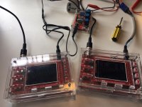
I finally had a little time this morning to look at this. Going very slow and methodicaly, i know i will find the problem eventually. My testing kit is fab - its two little oscilloscopes from Bangood (about $30 each with case) that came as kits and a simple little frequency generator (about $7 form Bangood - another kit, quite good fun to make) - it does the trick. PIC 1
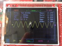
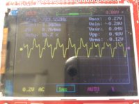
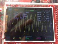
So pic 2 shows the input sine wave - 722 hz, 1.2v RMS straight from the signal generator. Pic 4 shows the good channel amplifying that input sine wave - 723.5hz, 3.94v RMS- so about 3.5 gain - volume knob about a third up. Pic 3 shows the same signal on the duff channel with the volume knob on the same setting - not even a sign wave and VRMS of 0.12v - so an attenuated single compared to the input and what a horrible waveform - but still at 723.5hz.
Todays tasks
1. Checked speaker wires for shorts- none found
2. Swapped all valves to see if the problem followed the valves - it didn't
3. Checked the pot i soldered in the other day - all good
4. Biased valves - problem still there
Tomorrow I will
1. Look at the transformer - you have given me some ideas there - is suspect the problem is here
2. Look at the pre amp signal to see if I am getting what i should - again thanks Jon for the ideas
if all that fails i will start tracing the signal and checked the components in the signal path for duff capacitors etc..
Weather still rotten here in Adelaide, so quite a fun project before the summer heat kicks in. Cheers!
I finally had a little time this morning to look at this. Going very slow and methodicaly, i know i will find the problem eventually. My testing kit is fab - its two little oscilloscopes from Bangood (about $30 each with case) that came as kits and a simple little frequency generator (about $7 form Bangood - another kit, quite good fun to make) - it does the trick. PIC 1
So pic 2 shows the input sine wave - 722 hz, 1.2v RMS straight from the signal generator. Pic 4 shows the good channel amplifying that input sine wave - 723.5hz, 3.94v RMS- so about 3.5 gain - volume knob about a third up. Pic 3 shows the same signal on the duff channel with the volume knob on the same setting - not even a sign wave and VRMS of 0.12v - so an attenuated single compared to the input and what a horrible waveform - but still at 723.5hz.
Todays tasks
1. Checked speaker wires for shorts- none found
2. Swapped all valves to see if the problem followed the valves - it didn't
3. Checked the pot i soldered in the other day - all good
4. Biased valves - problem still there
Tomorrow I will
1. Look at the transformer - you have given me some ideas there - is suspect the problem is here
2. Look at the pre amp signal to see if I am getting what i should - again thanks Jon for the ideas
if all that fails i will start tracing the signal and checked the components in the signal path for duff capacitors etc..
Weather still rotten here in Adelaide, so quite a fun project before the summer heat kicks in. Cheers!
Attachments
OK - so i am making progress. I could have the same fault as @JonSnell. My good channel is biased ok and balanced more or less across the anodes (still get fluctuating readings).
I thought i had biased the bad left channel well too - but clearly not..
The bad channel won't bias at all - it stuck on something like 15v when i want to see 55mV across my 1.1 ohm resistor to give me 50 mA. SO is suspect the bias pot is duff. Any one know the specs of these pots? I think i will replace them all..
All anodes show about 480v dc (i know, it can kill) so they look fine..
Going round the pins - comparing Right (good) with Left (bad) - i get
Pin Desc Right (good) Left (Bad)
1+5+7 Heater 53v 53v
2 Grid 1 of unit 2 -19.8v -15.2v
3 Grid 3 235v 235v
4 Cathode (grid3) 50mV 17.8v (!) - across a 1.1ohm resistor to ground
6 Grid 1 of unit 1 -21.2v -14.9v
All look within spec from what can see - but the left channel isn't biased at all.. so looking at the bias pot next..
any advice - much welcome! I know i can fix it - just crossing fingers that it isn't the output - transfomer - everything else is cheap and easy to fix..
Any where else i should be looking..?
hmm - removed the pot - it is a 4k7 - and it checks out just fine on my DVM! - yet when i turn it in the circuit it varies the voltage across my measuring resistor by very little..all in the mid to high teens V..
so it must be something upstream of the pot - will look at the circuit diagram and have a think..
so it must be something upstream of the pot - will look at the circuit diagram and have a think..
.. but looking at the circuit diagram, the pot has a 20v potential coming in, and i am reading close to that at the cathode - so it must be the pot... i will replace and see if that fixes it..
Annoyingly, i cant get to the back of the circuit board it is on as it carries the preamp tubes and seems to be welded to the chassis..
Annoyingly, i cant get to the back of the circuit board it is on as it carries the preamp tubes and seems to be welded to the chassis..
hmm - my heater voltage seems way to high doesn't it - i would expect 12.4 or 6.2v - i wonder if i had the DVM set correctly. Also, the pin 4 is the beam grid and oin5 is the cathode - and they are connected together and to ground.. so should show the same voltage.. i need to re measure these voltages..
Try replacing the 1.1 ohm resistor before you go any further. The fact that there is 17.8V across it means either 17A is flowing through it (impossible!!!!) or it is open. I assume that you are measuring across the resistor itself, if not make sure it is tied to ground at one end.
The bias voltages on both tubes are similar so that should have been a clue to look elsewhere.
The bias voltages on both tubes are similar so that should have been a clue to look elsewhere.
You were right - the 1.1 ohm resistor was showing 285k ohms on the DVM - so only passing a tiny current. I replaced the resistor, now when i turn on i get a rapidly increasing screeching sound which then goes low and loud so i turn off asap..
If i remove the cathode resistors i don't get the feedback sound. Not sure where to go next - any ideas anyone..?
If i remove the cathode resistors i don't get the feedback sound. Not sure where to go next - any ideas anyone..?
Did you perhaps inadvertently swap plate or grid leads when you were putting things back together?
Disconnect the feedback temporarily and determine whether this occurs again. Make sure the output transformer secondary is loaded with an appropriate power resistor!
If this does not result in the screech, reverse the plate lead connections, reconnect the feedback and try again. (Note if for instance you know that you only unsoldered the grid connections then swap those instead.)
- Status
- Not open for further replies.
- Home
- Amplifiers
- Tubes / Valves
- Fluorescing GU 29 tubes - whats wrong?