My El Cheapo-ish amp has a low frequency, say 1-4Hz (>10mV) variation over the power tube grid leaks when no signal is applied. It's not a single frequency, but some chaotic low frequency up-and-down-thingy (it doesn't look like an oscillation to me). The ripple/hum is ~ 1mV. In order to limit the number of variables I have pulled the output tubes.
It seems that the B+ is also fluctuating.
The amp sounds ok to me, but I haven't got a good reference. OT output seems ok on the scope. Is some common mode rejection helping me out?
Non the less, I would like to solve it, or at least understand it.
What could be the problem?
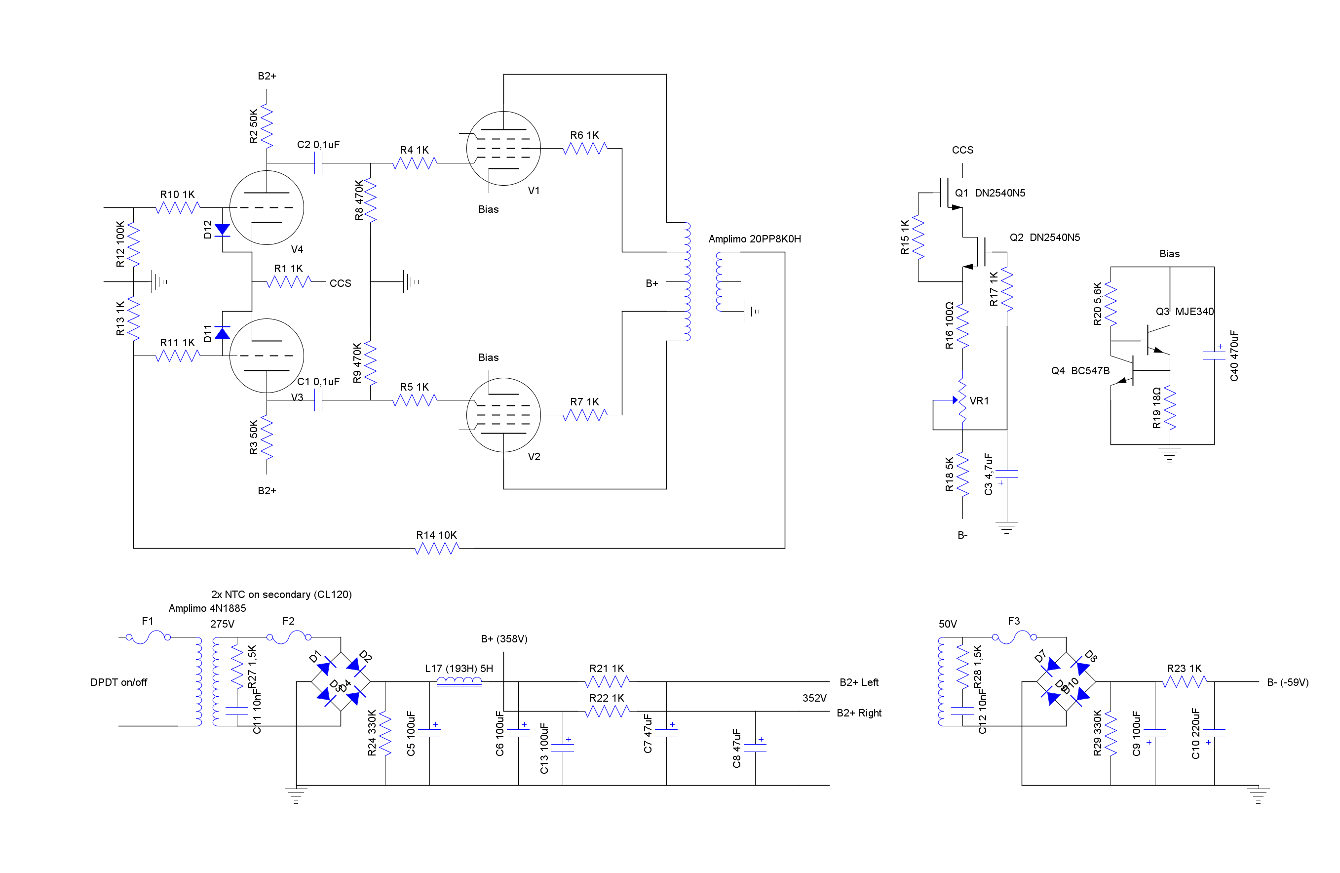
Part of my problem is that I still don't understand how an LTP with a CCS (with B- below 0V) works, despite searching online and reading Jones' book. Normally 'everything' is referenced to ground, but the LTP has no idea where ground is as far as I can see. As long as I don't understand that, I can't reason about it and don't think I will be able to tackle this problem.
It seems that the B+ is also fluctuating.
The amp sounds ok to me, but I haven't got a good reference. OT output seems ok on the scope. Is some common mode rejection helping me out?
Non the less, I would like to solve it, or at least understand it.
What could be the problem?
Part of my problem is that I still don't understand how an LTP with a CCS (with B- below 0V) works, despite searching online and reading Jones' book. Normally 'everything' is referenced to ground, but the LTP has no idea where ground is as far as I can see. As long as I don't understand that, I can't reason about it and don't think I will be able to tackle this problem.
From what you describe, i think it is the variation in mains voltage you are seeing, this is so low frequency it comes through the LC and RC filters with ease.
Mweh... I doesn't look like it. If that were the case, it would not drop faster than inbetween charging burst, right? Somehow, it doesn't look like that.
I put a video on youtube: ltp output - YouTube
I put a video on youtube: ltp output - YouTube
See if it is still there when you remove the driver tubes.
Appears to be a combination of rectification ripple and LF oscillation/noise.
The CCS has a high impedance for AC signals. When the grid #2 is grounded (no feedback),
the tube #1 AC current flows out of cathode #1 and into cathode #2, which is in the reverse
direction compared to tube #1. So there is a voltage polarity inversion at the #2 plate, but with
a similar amplitude since the plate resistors are equal. Then it functions as a phase splitter,
with equal but opposite polarity signals.
Last edited:
It definitely has ripple. I can alter that with my humdinger.
How do I solve the low frequency oscillation? I found stuff about motorboating, but as I have my output tubes pulled, I don't have the OT providing the inductance and I read somewhere you need three stages for motorboating.
Can I remove the driver tube? Will my CCS be OK? I put in some diode for this case (during startup), but can it function for quite some time that way?
Maybe just lift one end of each of the coupling capacitors instead, to be sure of no CCS problem.
That's easier than worst-case analysis of the circuit.
If this noise is present with the output tubes removed as you say, it is likely to be gone at the grid resistors
when the coupling capacitors are lifted. Probably it is due to the driver stage, but take a look.
Remember for AC signals, the voltage supplies are short circuits, and the CCS is an open circuit.
Also the LTP seeks its own bias voltage point with a CCS just the same, whether it goes to ground
or to a negative supply. The use of a negative supply is because of the needs of the CCS circuit
to function, and it may not be necessary in some circuits.
Last edited:
It's probably just 1/f noise (aka flicker/popcorn noise) in the grid current. That's pretty common and harmless.
Tom
Tom
Maybe just lift one end of each of the coupling capacitors instead, to be sure of no CCS problem.
That's easier than worst-case analysis of the circuit.
If this noise is present with the output tubes removed as you say, it is likely to be gone at the grid resistors
when the coupling capacitors are lifted. Probably it is due to the driver stage, but take a look.
Remember for AC signals, the voltage supplies are short circuits, and the CCS is an open circuit.
Also the LTP seeks its own bias point with a CCS , whether it goes to ground or to a negative supply.
What would lifting the coupling caps do, other than change the load of the LTP?
What is the worst-case analysis you are talking about?
When the coupling caps are lifted, the (top of the) grid resistors will be floating. I agree the noise will be gone. I measured (mostly) across the power tube grid resistors as they have safe low voltage across them i.s.o the LTP plate resistors or the B+ itself. Input of LTP is zero and current through LTP is fixed (drop across plate resistors should be fixed also), so I guessed any B+ variation should be on the grid leak of the power tube (filtered by the RC filter of course).
I hear what you say about the LTP with CCS; it just doesn't make sense to me...
Think of the LTP as like an op amp, just without the output stage (which functions
as a balanced to single ended converter).
If the noise is at the input plates (with the output tubes removed), then it could be any combination
of noise from the tubes, resistors, current source, or the power supplies. You'll very likely find that
the noise at the two input plates is not identical (though similar).
Last edited:
I think I had a kind of an aha-erlebnis. I felt as if I had a variable too many (cathode voltage), but that one is used to give zero output for any equal voltage at the inputs: a differential amplifier a.k.a. opamp 🙂
As a great Dutch soccer player once said: "You'll only see it when you get it."
Off to bed. See if it still makes sense tomorrow.
As a great Dutch soccer player once said: "You'll only see it when you get it."
Off to bed. See if it still makes sense tomorrow.
It's easier to understand if you assume balanced input drive to an LTP (for the no-feedback case).
Then since the circuit topology is symmetrical, the cathode must be at 0V AC.
If instead (still no feedback) the grid #2 is grounded (at 0V AC), then the cathode has an AC potential
of Vin/2 because of the symmetry of the circuit. In this case, the Vin/2 is a common mode voltage.
Then since the circuit topology is symmetrical, the cathode must be at 0V AC.
If instead (still no feedback) the grid #2 is grounded (at 0V AC), then the cathode has an AC potential
of Vin/2 because of the symmetry of the circuit. In this case, the Vin/2 is a common mode voltage.
Last edited:
Just realized the small spiky stuff can't be rectifier ripple, but must be hum because it is affected by the hum dinger.
That means that my argument against mains variations doesn't hold anymore.
That means that my argument against mains variations doesn't hold anymore.
- Home
- Amplifiers
- Tubes / Valves
- Fluctuating B+