maybe this article will help?
EDN PDF ("Bootstrapping your op amp yields wide voltage swings" King, Watkins; Analog Devices)
I doubt many here have played with these style circuits although a very few audio power amps have used monolithic op amp front ends
to include LtSpice circuits I just append .txt to the file name
you can also capture the screen and crop in a "paint" program, use .png for line drawings - not .jpg
Last edited:
I built a bootstrapped op amp based power amp about five years ago.
Always liked the idea of building a power amp that consisted basically of an op amp plus the output pair! There are of course other techniques to achieve something close to these aims.
It measured generally pretty good but as may be expected, the clipping performance was a bit strange!
It sounded distinctly average as far as I remember.....
you can float the output supplies (but you need a dual for each channel) and take all of the V gain in the output Q, allowing low V opmps for the front end
http://www.diyaudio.com/forums/solid-state/101602-qsc-clones-backwards-amps.html#post1205743
for more fun you should look at Prof. Cherry's articles and comments on this output stage - he has a JAES article claiming there is no difference in achievable output characteristics with this floating ps CE vs the more traditional fixed ps EF output stage except that the gain "tied up" in the inherent unity gain local feedback of the EF is now available to the global loop and can be used to get the same ouput impedance, distortion and stability as the EF output
Thanks,
In Fact there is not the MAIN (power) PSU floating as in the QSC, but everything before that (input and drive of the power BJTs) and these have a small (+/-9V) supply floating around the speaker output.
this way you get very similar driving like in the case of the QSC, but you dont need separate BIX Xformers (or windings)
my goal was to have similar sounding amp like the QSC you mentioned but with shared PSU and with smaller parasitic capacitance (small) floating PSU.
I am curious if it sounds similar to PL4.0, where the xformer is small (becouse of 115kHz SMPS) and the sound is very sweet...
thanks for the information guys,
Tamas
you can also capture the screen and crop in a "paint" program, use .png for line drawings - not .jpg
I try it 🙂
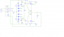
here we go:
Attachments
Hi Tamas
There is a slight problem right at the input.
R1, R2, R17 and R18 apply a little more negative feedback than positive feedback to the opamp.
It will work as you have drawn it, but it relies on a very low source impedance to get the correct ratio of negative and positive feedback.
I suspect if you put a 1K or 2K resistor in series with the signal source (V1), you will see some very bad behavior.
Cheers - Godfrey
edit: I just saw your spice file has the input connected differently.
That looks like it will behave better, but have very low input impedance. The circuit in post 6 has negative input impedance. That's the one I was referring to above.
Last edited:
Hi Tamas
There is a slight problem right at the input.
R1, R2, R17 and R18 apply a little more negative feedback than positive feedback to the opamp.
It will work as you have drawn it, but it relies on a very low source impedance to get the correct ratio of negative and positive feedback.
I suspect if you put a 1K or 2K resistor in series with the signal source (V1), you will see some very bad behavior.
Cheers - Godfrey
edit: I just saw your spice file has the input connected differently.
That looks like it will behave better, but have very low input impedance. The circuit in post 6 has negative input impedance. That's the one I was referring to above.
Hi Godfrey,
Yes, there is a difference indeed 🙂
ANyhow, when I try to modell it i get strange results, showing that I can not have positive sinus above 28V independet from HI power Rail voltage, while negative seems to be OK.
I was trying to build it today, without connecting the high power Voltages, just to see biasing etc, but the OPamp's output is always on the Rail... and so the pnp driver transistor is getting hot in 5sec while the npn is cold. unfortunately i had no time to measure the DC values becouse of the very quick warming.
strange....
I will try once again tomorrow.
cheers
Tamas
Last edited:
That is a very fast op-amp. Perhaps there is high frequency instability or oscillation?
A small capacitor (perhaps 100pF to 1nF) between the op-amp's output and inverting input may help.
A small capacitor (perhaps 100pF to 1nF) between the op-amp's output and inverting input may help.
That is a very fast op-amp. Perhaps there is high frequency instability or oscillation?
A small capacitor (perhaps 100pF to 1nF) between the op-amp's output and inverting input may help.
I was building a second prototype based on a suggestion of a friend where all the surrounding resistors and psu decoupling 100nF capacitors around the THS4011 were built with SMD parts very near to the chip. a feedback capacitor of 4.7pF was also used,and the circuit works very well.
I just wanted to give a short update about it.
Sofar I am happy with the results. Listening tests are comming hopefully next week...
cheers,
Tamas
- Status
- Not open for further replies.
- Home
- Amplifiers
- Solid State
- floating supply class AB will it work? is it any good?