I tried the circuit at the bottom of this page The Valve Wizard -Long Tail Pair and it's garbage. Over 3v difference between phases. I don't think I've ever got anything off that site to work right.
They don't work right because triodes are low gain devices, unlike transistors. You need adequate tail loads to get a trioded LTP to balance as it should. That means active tail loads, and I prefer cascoded BJTs (high gain devices) for that. I haven't had any problems with phase-to-phase balance with active tail loading.
Vi1/Vi2= 1 - 1/(gmRtail) for any LTP
With transistors, you can easily drive gm up, even with short, passive tails. With hollow state, your gm is limited, and balance can be improved only by maximizing Rtail with active loading.
The ones you posted, I don't see how either of them use fewer components. The first would add 4 additional tubes, the second would add 3 (if they were all dual triodes). Due to the reason explained below, I need to use at little tubes as possible.
This is for a battery powered project using a 12vdc to 300vdc SMPS.
You asked for examples. You can implement an LTP with one dual triode, and you mentioned 12AX7s. These should be good for AV ~= 30. If you want to minimize the number of bottles, then a good alternative would be a pentode/triode such as the 6KE8: use the pent as a voltage amp driving the triode operating as a cathodyne splitter. If your finals are something like 6AQ5s or 6V6s operating as pents, that should give adequate drive while maintaining headroom.
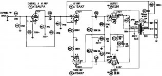
Here's a circuit I'm emulating and for the life of me I can't figure out how to adjust the gain of the second tube. I would think R9 would control the gain but that's also the grid resistor for the output tube. I would have to change R6 as well to keep the output tubes grids the same impedance.But that puts me back where I started.
Your circuit reminds me of the Pilot 232 circuit, minus the 12AU7 line stage section. It's not a "floating" paraphase but still paraphase. The value of R66 is crucial to the balance of the two phases. I would use 220kΩ for R69 in series with a 50kΩ pot to equate 270kΩ of R72 as the grid leak. Adjust wiper of pot to get the balance.
The Pilot 232 is one of the few best sounding 6BQ5 amps I've heard. I implemented the circuit on a Heathkit integrated amp and it sounded terrific.
Attachments
Thank you for that. That just showed me how easy it is to apply negative feedback to this type of PI when a common cathode resistor is used.Hi, looks like you don't like too many parts. Check out this schematic:

directdriver - That looks ALOT like the Magnavox circuits which also sound very good to me but Magnavox does some really weird stuff with it. Your right about the values though. The standard paraphase is picky. The floating paraphase, on the other hand, seems very forgiving in the emulator. I can just about change any value 10% or even 20% with minimal effect on the gain or balance.
jerluwoo - I tried a cathodyne PI and couldn't get enough gain out of it driving 6BQ5s or 6V6s, but, between that and a paraphase, the cathodyne was much less microphonic and had less noise but that could be due to the lower gain. If I could afford the heater current I'd build a Williamson.
Being a portable or mobile amp, "absolute perfection" is not required but I'd still like it to sound as good as it can with minimal components. Having heard other paraphase amps (Magnavox and Setchell Carlson) and floating paraphase amps (Motorola), I was content with the sound. I'm leaning towards the floating paraphase mainly because of it's stability over time.
Last edited:
jerluwoo - I tried a cathodyne PI and couldn't get enough gain out of it driving 6BQ5s or 6V6s
The gain needs to come from the first stage. Let's run some numbers: Assume you have EL84/6BQ5 or 6V6- that will require about 10V (worst case) at the grids for full power. The first stage can easily be designed to give you an open loop gain of 38dB (80x) with a triode, even more if you use a pentode. If you want a 1.5V sensitivity at the input (a very typical value), that corresponds to an output of 120V to the cathodyne. The cathodyne might have a gain of 0.9 to each output, so that's 108V to the grids. This means you have 108/10 = 20dB of gain available for feedback. Gain should not be an issue.
You'll also have a lower source impedance to the output stage, better balance across the bandwidth, and greater stability over time and with tube aging and changes.
I suspect that assumes infinite mu, which is a reasonable approximation for a BJT but not a valve. Low mu makes LTP imbalance worse, because it reduces differential-mode gain but leaves common-mode gain almost unchanged.Miles Prower said:Vi1/Vi2= 1 - 1/(gmRtail) for any LTP
 How good is the quality?
I'm trying to design a PP amp with minimal components.
A key advantage of a self-split is the elimination of the phase-inverter tube(s) for a push-pull output stage - perhaps that meets your 'minimal' criteria, especially if you use triode/pentode tubes such as 6GW8/ECL86.
The driven push-pull tube operates only in Class A, and the other tube has a cloned signal applied to it - so it doesn't push quite the same max output power level that one is used to seeing for Class AB.
Unfortunately for the self-split brand name, many circuits use very non-linear techniques to generate the cloned signal, such as a signal derived from the varying screen current of the driven tube. A pretty common and simple technique uses a common cathode resistance and grounded grid to generate the clone signal. I just came across a Philips amp using fixed back bias, where the cathodes were connected to the speaker output winding to generate the clone signal – that seems pretty simple and linear too. Linearity in class A is assisted by not pushing in to grid-conduction or cut-off region, which trades off output power a bit.
^ open twisties packet in cinema at both ends and sit back
Last edited:
So far so good. It works. I think my salvaged output transformers may not be that great. In my listening test; Separation is good. Treble is clear and sparkly. Mids are too loud. Mid-bass is thin. Bass is weak but extends fairly low. NFB seemed to only effect the volume but didn't change the tone.
I have another pair of output transformers to try although I'll be ordering Edcors sometime soon.
If you look at the schematic in the first post, each of the 12AX7 cathodes have their own cathode resistor. I currently have it wired as shown below. What are the pros/cons to having a single cathode resistor? I'm guessing that the shared load alternates back and forth and the use of a capacitor isn't needed. Is that correct? Or should I have the cap (C4) in parallel?
Attachments
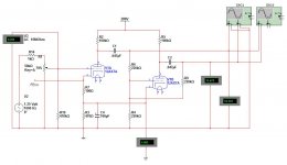
I currently have it wired as shown below. What are the pros/cons to having a single cathode resistor?
A single unbypassed resistor will introduce some positive feedback. Not necessarily dangerous, but it gives me the willies nonetheless.
Your PI is still rather unbalanced, due to R4.
It dawned on my to measure the AC voltage on R3 and there's only 10mv when the circuit is putting out 30vac per phase. That's what I had assumed.
Adjusting only R4 didn't help balance the PI. It's a combination of R4 and R9. Lowering R4 and raising R6 helped but the values start to get really touchy.
Adjusting only R4 didn't help balance the PI. It's a combination of R4 and R9. Lowering R4 and raising R6 helped but the values start to get really touchy.
Adjusting only R4 didn't help balance the PI.
You don't adjust it, you get rid of it! Throw it away! That resistor is why it's so bloody touchy!
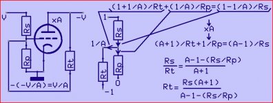
The circuits of Merlinb May 2006 and Cassiel Feb 2014 didn't have the R4 to GND.For such case I showed the relation of the two resistors in function of the tubes gain.
Your last one did have a resistor to GND.That changes things.A drawing + formula derivation.
Mona
Your last one did have a resistor to GND.That changes things.A drawing + formula derivation.
Mona
Attachments
You don't adjust it, you get rid of it! Throw it away! That resistor is why it's so bloody touchy!
If I "eliminate" R4 (as in remove it) then there's no grid resistor on V1B.
If I "eliminate" R4 (as in short it) then V1B's grid is grounded.
Can you elaborate?
The circuits of Merlinb May 2006 and Cassiel Feb 2014 didn't have the R4 to GND.For such case I showed the relation of the two resistors in function of the tubes gain.
Your last one did have a resistor to GND.That changes things.A drawing + formula derivation.
Mona
Both drawings have an R4 from V2B grid to ground. The main difference between the schematic in the first post and the second one was the common cathode resistor.
__________________________________________________________________
As for the bypass cap; My emulator didn't show any difference when I bypassed the cathode resistor when both triodes share a single resistor. As per Merlinb's suggestion, I tried adding it in my amp. It make a big difference and a noticeable increase in gain.
The lack of "fullness" that I was describing in post #35 was due to my output transformers. I got my much larger Motorola OPTs wired in today and WOW. Those Setchell Carlson OPTs were just awful.
One thing I noticed right away was the floating paraphase has less microphonics then the standard paraphase. Could that be due to the second triode running "wide open" in a normal paraphase? The floating paraphase second stage's gain is much less due to the local feedback around the tube correct?
Last edited:
- Status
- This old topic is closed. If you want to reopen this topic, contact a moderator using the "Report Post" button.
- Home
- Amplifiers
- Tubes / Valves
- Floating Paraphase.