Hi Folks:
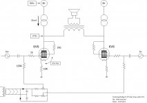
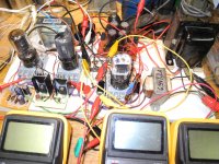
Taking inspiration from John Broskie’s TCJ blog no. 192, OUTPUT STAGE DESIGN, and Pass’ Aleph X, I put together the following today on a piece of plywood. It works just fine, although I don’t have much to compare it to or know if there are any particular technical merits.
One thing Broskie says about this form of bridging is that it “never leaves half of the primary flapping in the wind”. Seems like a good thing but I don’t know if that really matters. Maybe there are some other advantages – like being able to use a simpler output transformer?
I’m hoping someone with more knowledge could comment before I take it any further. Maybe this has been beat to death elsewhere?
If there’s enough interest I can post the whole circuit showing the MOSFET+BJT CCS I pieced together.
Attachments
The problem is, if the plates voltages become unbalanced DC starts flowing across the primary. this will rapidly cause transformer saturation.
You need a DC blocking cap at one end of the primary, something in the order of 4-10uf would probably do.
Shoog
You need a DC blocking cap at one end of the primary, something in the order of 4-10uf would probably do.
Shoog
Last edited:
Using CCS circuits makes it quite inefficient power wise, unless you actively (by signal) control the current output of the "CCS's".
Using both sides of the primary is helpful in that the output leakage inductance of an OT is from the driven primary side to the secondary. Driving both primary sides will then lower the leakage L by half (for better HF extension thru the OT). But ordinary class A does the same thing.
A circlotron configuration can drive both primary sides, and in class AB as well. The "elliptron" configuration, or Norman Crowhurst's Twin Coupled configuration can drive two sides at once also (but the twin still has two unused sides at any time), and can be configured for a single B+ supply (unlike Circlotron). The McIntosh config. is somewhat similar.
I'm still trying to figure out the point of this circuit, what the actual benefits are. Is it just one more case of, "When you don’t know what you’re doing, try something different"?
it wastes tube capacity at the full on state as the CCS stays on taking that current flow from the output transformer
I don't see any advantage, a few disadvantages really, unless you are trying to use say an ungapped power transformer for the output. Would add a 1000v diode reversed biased across your current sources to make sure they don't get fried by the inductive load swinging the output voltage above B+.
OK, this has been really interesting, and the outcome is clear. Was a pleasant afternoon putting it together and I learned a lot while doing it. I appreciate the instructive insight. Have successfully built an Atma-Sphere M60 OTL, Hans Beijner’s OTL, an Aleph J-X, and Aleph P v1.7, but sometimes I go off on tangents like this.
But before leaving the subject entirely -
Shoog: Is the unbalanced plate condition you mention the same as in a conventional class A when one tube ages differently than the other causing unbalanced or net current flow through the primary – or is it some other condition?
clip: “stocktrader200: it wastes tube capacity at the full on state as the CCS stays on taking that current flow from the output transformer” - The mental exercise I did was to consider the full on state with one tube fully on and passing 2 x Iq and the other just off and passing 0 x Iq In a conventional class A that 2 x Iq flows through half the primary (or ¼ the primary impedance) while in this version 1 x Iq flows through the full primary (or 1x the primary impedance) – which should mean the same power is being transferred into the core in either case (P= I^2xR) while both cases flowing a total of 2 x Iq from the power transformer. i.e. no excess load on the power transformer. Is that right or did I misunderstand your point? (likely)
However, as smoking-amp points out, the big waste is the large voltage drop (power dissip.) over the CCS. Yech. I have to go read more about leakage inductance to understand your other points. My simple thinking focused on the absolute current through the single primary being the same as the net current through the conventional split primary with the same magnetizing effects. Clearly that’s only part of the story.
jerluwu: That’s the only advantage I could see also, which isn’t much of an advantage.
I think it’s unanimous, and apologies if anyone mad their time was wasted.
But before leaving the subject entirely -
Shoog: Is the unbalanced plate condition you mention the same as in a conventional class A when one tube ages differently than the other causing unbalanced or net current flow through the primary – or is it some other condition?
clip: “stocktrader200: it wastes tube capacity at the full on state as the CCS stays on taking that current flow from the output transformer” - The mental exercise I did was to consider the full on state with one tube fully on and passing 2 x Iq and the other just off and passing 0 x Iq In a conventional class A that 2 x Iq flows through half the primary (or ¼ the primary impedance) while in this version 1 x Iq flows through the full primary (or 1x the primary impedance) – which should mean the same power is being transferred into the core in either case (P= I^2xR) while both cases flowing a total of 2 x Iq from the power transformer. i.e. no excess load on the power transformer. Is that right or did I misunderstand your point? (likely)
However, as smoking-amp points out, the big waste is the large voltage drop (power dissip.) over the CCS. Yech. I have to go read more about leakage inductance to understand your other points. My simple thinking focused on the absolute current through the single primary being the same as the net current through the conventional split primary with the same magnetizing effects. Clearly that’s only part of the story.
jerluwu: That’s the only advantage I could see also, which isn’t much of an advantage.
I think it’s unanimous,
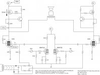
and apologies if anyone mad their time was wasted.The center of the primary is effectively at AC ground, so if you ground that point you can eliminate one side. Then move the 2nd tube over in place of the CCS to form a totem pole output and drive it's grid with a bootstrapped drive signal. This will use the full primary at all times, and use the tubes efficiently as well. No CCS's needed.
Some configurations:
The Tube CAD Journal, Totem-Pole Output Stage
Gomez Vs XPP Amplifier
Some configurations:
The Tube CAD Journal, Totem-Pole Output Stage
Gomez Vs XPP Amplifier
Last edited:
OK, this has been really interesting, and the outcome is clear. Was a pleasant afternoon putting it together and I learned a lot while doing it. I appreciate the instructive insight. Have successfully built an Atma-Sphere M60 OTL, Hans Beijner’s OTL, an Aleph J-X, and Aleph P v1.7, but sometimes I go off on tangents like this.
But before leaving the subject entirely -
Shoog: Is the unbalanced plate condition you mention the same as in a conventional class A when one tube ages differently than the other causing unbalanced or net current flow through the primary – or is it some other condition?
clip: “stocktrader200: it wastes tube capacity at the full on state as the CCS stays on taking that current flow from the output transformer” - The mental exercise I did was to consider the full on state with one tube fully on and passing 2 x Iq and the other just off and passing 0 x Iq In a conventional class A that 2 x Iq flows through half the primary (or ¼ the primary impedance) while in this version 1 x Iq flows through the full primary (or 1x the primary impedance) – which should mean the same power is being transferred into the core in either case (P= I^2xR) while both cases flowing a total of 2 x Iq from the power transformer. i.e. no excess load on the power transformer. Is that right or did I misunderstand your point? (likely)
However, as smoking-amp points out, the big waste is the large voltage drop (power dissip.) over the CCS. Yech. I have to go read more about leakage inductance to understand your other points. My simple thinking focused on the absolute current through the single primary being the same as the net current through the conventional split primary with the same magnetizing effects. Clearly that’s only part of the story.
jerluwu: That’s the only advantage I could see also, which isn’t much of an advantage.
I think it’s unanimous,
Yes thats what I mean.
Shoog
Sorry about any misundstanding, I just meant to say that each tube has to drive a CCS plus the output transformer.
Well, there is another merit of this configuration. You cant see it clearly from the schematic, but you have eliminated the powersupply (cap) from the signal path. if you could make it dc coupled, there would be no capacitor in the signal path. I would be happy to sacrifice some power in the ccs for that. Also, i think it cancels distortion because both tubes function in opposite way.
Paul
Paul
Oh and please keep on experimenting. You'll learn a lot more this way as opposed from building a standard amp.
Paul
Paul
I'm making something something like this. Half the circuit with parafeed output cap and cathode feedback. I was given 20 100V trafos so had to think up something for using them. What FET did you use?
- Status
- Not open for further replies.
- Home
- Amplifiers
- Tubes / Valves
- Floating Bridged CCS Loaded P-P Tube Amp