So, my 7yr old daughter has been blasting some old CDs we had in the basement, and I have meant to build her some sort of audio system but life, work, etc etc... When I exclaimed at how crappy it was, she got upset that I was threatening her precious lil music box, so I had to explain to her WHY it was so bad and that I wanted to do a project together. That got her interest piqued! I did look into off the shelf units, but at $3-600+ for anything halfway decent, I figured we can learn and build a project together for that and have a much better system in the end.
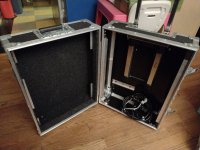
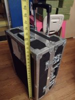
I was initially planning to build the PE blast box into an armored case she could carry around, but reviews were not kind. Then I remembered the armored flight case I had lying around in my garage for years. It's about 15"w x 20"t and each half is 4.5" deep. The handle takes up a little extra volume on one side, but I can balance that out. With that and other components taking up space internally, it'll be about 0.5cuft which is perfect for an 8" sub.
I wanted to keep it simple, and I've been thinking about full range for a while, but there's obviously no way I could stick a voigt pipe in there. I found the Dayton Epique 7" extended range sub which seemed perfect. If I put the electronics outside the box, it's just big enough for a ported box with that driver and a low response tweeter, but the availability went from "in stock any day" to "in stock in July." Her birthday is May 20. Then I started finding and learning about open baffle which would have been perfect. I'll not go into details here, but it would have been really cool to have dual long throw 12s bumping on either side with the magnets hanging out the back, not to mention the ease of building it. I had an entire plan worked out, but every component was like, "well that's a little more than I wanted to spend, but for my daughter..." until I decided to add up what I had planned and came to a whopping $1500!!! My budget was supposed to be about $500 max.
So then I decided to go back to the drawing board for the umpteen millionth iteration, but this time with a strict budget in mind, and no complicated modification of the box (bigger than 8" driver would require the handle to be worked around or removed). I found what looks like a very decent sub-mid range driver capable of well into 1500hz in the $50 Dayton 8" DVC sub. Handles 80W with the same on the 1,1/8" aluminum dome tweeter at 4ohms (with built in grate/guard), perfect for a US Acoustics Lisa car audio amp which has really nice built in crossovers that go remarkably high for a car amp (3.5khz). Along with a 350W meanwell supply and a lithium car battery, this should be quite flexible in use, from home to car to battery powered at the park, etc.
All I want is decent sound with some nice thump with bluetooth 5.0 or headphone input. No volume knobs, no controls, nothing complicated, based on common 12V car audio. Just set it so you can connect to it and use the source for volume control. I think this will work nicely. Here's the component list so far, should be in this week in time for her birthday on the 20th:
I was initially planning to build the PE blast box into an armored case she could carry around, but reviews were not kind. Then I remembered the armored flight case I had lying around in my garage for years. It's about 15"w x 20"t and each half is 4.5" deep. The handle takes up a little extra volume on one side, but I can balance that out. With that and other components taking up space internally, it'll be about 0.5cuft which is perfect for an 8" sub.


I wanted to keep it simple, and I've been thinking about full range for a while, but there's obviously no way I could stick a voigt pipe in there. I found the Dayton Epique 7" extended range sub which seemed perfect. If I put the electronics outside the box, it's just big enough for a ported box with that driver and a low response tweeter, but the availability went from "in stock any day" to "in stock in July." Her birthday is May 20. Then I started finding and learning about open baffle which would have been perfect. I'll not go into details here, but it would have been really cool to have dual long throw 12s bumping on either side with the magnets hanging out the back, not to mention the ease of building it. I had an entire plan worked out, but every component was like, "well that's a little more than I wanted to spend, but for my daughter..." until I decided to add up what I had planned and came to a whopping $1500!!! My budget was supposed to be about $500 max.
So then I decided to go back to the drawing board for the umpteen millionth iteration, but this time with a strict budget in mind, and no complicated modification of the box (bigger than 8" driver would require the handle to be worked around or removed). I found what looks like a very decent sub-mid range driver capable of well into 1500hz in the $50 Dayton 8" DVC sub. Handles 80W with the same on the 1,1/8" aluminum dome tweeter at 4ohms (with built in grate/guard), perfect for a US Acoustics Lisa car audio amp which has really nice built in crossovers that go remarkably high for a car amp (3.5khz). Along with a 350W meanwell supply and a lithium car battery, this should be quite flexible in use, from home to car to battery powered at the park, etc.
All I want is decent sound with some nice thump with bluetooth 5.0 or headphone input. No volume knobs, no controls, nothing complicated, based on common 12V car audio. Just set it so you can connect to it and use the source for volume control. I think this will work nicely. Here's the component list so far, should be in this week in time for her birthday on the 20th:
- Dayton Audio bluetooth 5.0 module (small amp built in, but I'm only interested in the RCA output). I plan to install and wire this inside of the amp leaving it's inputs open.
- Dayton 8" DVC sub
- Dayton 1.125" reference aluminum dome tweeter
- US Acoustics "Lisa" 200W A/B car amp crossed over at 1500hz.
- Meanwell 15V 350W power supply, adjusted down to 14.6V
- Valence U1-12RT battery, 12.8V 40AH with continuous discharge of 30A, 80A peak. These come from medical carts replaced every year regardless of use and often not much at that for just $170 on ebay.
- A 2F power cap with volt meter. I know these are passé for car audio when you really just need a bigger alternator, but the meanwell doesn't have very big power caps in it, and it may not be able to keep up with peak power drains on heavy bass which could cause the volume to waver a bit and/or stress out the supply, so this is actually a very good use for these otherwise useless car audio pieces. Bonus with the volt meter to display battery voltage.
- And, instead of wiring in a dedicated 3.5mm jack, I figured, with the RCA inputs exposed and the BT module tucked away inside the amp, it would be better to have a 3.5mm to RCA cable anyway that can simply be tucked away when not in use.
Have you made the purchases yet?
Have you seen the Boominator thread? The original concept was good, and it has had many years of development - and clones and variants.
Different versions exist in multiple countries at multiple price points, so there should be a build that suits you / that you can streal.
The original thread is here:
https://www.diyaudio.com/community/threads/my-first-diy-pa-system.374970/
A recent discussion of the same idea:
https://www.diyaudio.com/community/threads/my-first-diy-pa-system.374970/
For me, the main takeaways are:
1) smooth, fairly efficient midbass drivers might "win" compared to something marketed as a sub
"It's better to have a good middle bass performance to compensate for the lack of real sub-bass."
2) You can look at prior builds / galleries for design tips, even if you use totally different parts (e.g. using the woofer frames as part of the structure is genius).
3) Efficiency of your components is important if you want to a compact system with a long battery life.
e.g. the "Lisa" is a class AB amp, and these waste power as heat. Boominators usually use class D amps, which run much cooler (so longer battery life, and you have more options for where to mount them).
e.g. the Dayton sub gives 86dB / watt. An equivalent midbass will be several dB louder, which will again equate to more battery life.
"Lisa" is a class AB amp, and these waste power as heat. Boominators usually use class D amps, which run much cooler (so longer battery life, and you have more options for where to mount them).
As an electronic repair tech who constantly deals with bad design decisions, the story regarding US Acoustics really spoke to me. Apparently, they went out of business and their repair tech took up the banner with his own products. They reportedly are a very good value and conservatively rated.
Battery life was the lowest priority design goal here. Sound quality was paramount, and I wanted to experiment with using a sub that has advertised response into 2k as a sort of full/extended range sub with a low responding tweeter. The Lisa was perfect with built in crossovers into 3.5khz, which is strange for a car amp (I plan to cross at 1.5k), and I saw this as hard evidence of their superior design.
It will mostly be plugged in around the house or into the car/van at camp sites. I also don't need it to be super loud. I'll be setting the max volume on the amp to be a reasonable house volume. This may have the look of a small PA box, but it's far from the design intentions. I'd rather have clean, flat response down into 30hz or so than have loud efficiency with 1-10% distortion from a class D.
Due in tomorrow. Thanks for the references (which I am checking out), but I tend to dive into my own designs head first. That boominator looks to be using a compression/horn driver which I had considered, but I couldn't find one in my price range that had decent response. I also wanted a wide dispersion that I didn't think a horn driver could do. I did consider going for more of a mid bass driver, but...Have you made the purchases yet?
I hate to disagree with you, but imho, there's no compensating for a lack of sub bass 😎 especially with today's music. That was the second most important design consideration, having some thump. An 8" driver with a good strong motor should be able to do mids with ease, and whereas the other Dayton "subs" are true subs, this one (and the Epique I wanted) had very flat response into 2khz as well as power handling in the same 80W range as the tweeter I chose and only a bit more than the 50W the amp puts out (which is probably conservative). I'd rather have some thump that maxes out headroom and compensate with lower volumes than sacrifice on thump for volume and efficiency.smooth, fairly efficient midbass drivers might "win" compared to something marketed as a sub
"It's better to have a good middle bass performance to compensate for the lack of real sub-bass."
Nah, this is the perfect time to disagree 🙂 it seems like your choices are good for your specific goals.I hate to disagree with you, but imho
My only note/correction is that you can get class D amps that are not "1-10% distortion".
e.g. the TA-10 was a cheap and popular (low power) amp made about 15 years ago. It has low distortion + a slightly better SN ratio than the Lisa.
Look at party speakers, they start about $30 here, to $300.
Basically powered speakers on a trolley, some with battery too.
The amp is built in, and some can use an external 12 V supply as well.
Their look and specifications will give you some new ideas before you actually build the unit.
Basically powered speakers on a trolley, some with battery too.
The amp is built in, and some can use an external 12 V supply as well.
Their look and specifications will give you some new ideas before you actually build the unit.
I do like the international carry-on suitcase sized speaker.
Design a good handle for it, Wheel it around for portable use; then when you’re done, wheel it home; pull out the carry handle, turn it upside down and now it has its on integrated handle stand
Plug it into charge in the battery and simultaneously use it as a home speaker
Design a good handle for it, Wheel it around for portable use; then when you’re done, wheel it home; pull out the carry handle, turn it upside down and now it has its on integrated handle stand
Plug it into charge in the battery and simultaneously use it as a home speaker
Well, poop nuggets! I just opened a huge box from PE and looked at my new US Acoustics Lisa amp to find that the low pass has been changed to a max of 250Hz instead of the 3500 as is still advertised on both PE and their website and sell sheets. I sent them an email to see if it's an easy component/jumper change I can do. Kinda disappointed here. It was also supposed to come with "Docking Pads® to reduce vibration" but all I got was screws.
I just made these RCA jumpers to go from the chnl 1&2 outputs into the chnls 3&4 inputs. Made with Switchcraft 3502RAAU right angle cable connectors that I got from ebay for about $8 each (and wasted a couple in the process, oops). Used a pipe cutter to cut down the threaded tube. Then just used a hacksaw to go through the threads about halfway being careful not to damage the plastic isolation inside. I couldn't fit a wire inside, so I just added a dab of solder on each side to contact each other when they get screwed together. Works great! And now that I've made them, I realized that since I was planning to break the warranty by opening up the amp and installing the PE bluetooth module inside, I could have simply wired them together internally, but this looks cool and protects the RCAs from the weather.

Proof of concept setup works! Even without a low pass for the woofer at 1500hz (currently giving it full range) it sounds great! The woofer does confirm it's advertised response with a slight dip at 1200 and sone wild differences above 2k, but the tweeter more than makes up for the dip as well as all muddiness of vocals. In fact, with bass boost at max, it sounds really great just sitting on my table free air! I'm really surprised by the free air response. It's tempting to just slap them in the box lol, but it can't be very loud like that without maxing out. But that lack of bottom end should clear right up in the ported box. Vb should be about a 0.6cuft and with an 11"x2" double flared port, should be tuned about 34hz.
And I am thoroughly impressed with service from US Acoustics (and Parts express who offered me a free filter/s). When I emailed them about the mis-advertised low pass (they recently changed the design from 3500 to 250hz), they sent me the silk screen and which resistors to change to get a 1500 LP! Parts express didn't have any filters in my range, but that's for the best without large external filters.
And I taught my daughter how to solder and made her tin wires and hook all of this up, and when we got it going, she said, "I can hear things in that I've never heard outa my stereo!" Yup, she's hooked!

Wow, I just checked DC power consumption (14.6V), and blasting at full volume, I'm only seeing 5amps max! Moderate volume is hovering around just a measly 1A. That's only one side hooked up, but still, I don't think this thing will even ever top 15amps. That means I only need one of the Bluetooth Power Sonic 9AH batteries I was planning to use 2 of and it should last 1-4hrs which is fine for this, and can always go more.
Very nice to build this with your daughter and good soldering skills last for a life time!Wow, I just checked DC power consumption (14.6V), and blasting at full volume, I'm only seeing 5amps max! Moderate volume is hovering around just a measly 1A. That's only one side hooked up, but still, I don't think this thing will even ever top 15amps. That means I only need one of the Bluetooth Power Sonic 9AH batteries I was planning to use 2 of and it should last 1-4hrs which is fine for this, and can always go more.
The reply from US Acoustics said to simply change R18, 31, 38, & 40 to 2.2kΩ in order to get 1500hz low pass instead of 250. That's not the advertised 3500, but it turns out for the best I think, at least with the current design.
But of course I couldn't take that at face value. No, I had to waste an entire day on reverse engineering the circuit to figure out if this was ideal. The filter is rather simple once you find it and cut off all the junk, but it's oddly setup from examples I googled, so I couldn't just find a simple calculator. Instead, I found Circuitlab.com which I confirmed was modeling correctly since it matched both the original specs and the new one by changing the resistors.
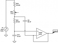
Knowing the model works with the filter removed from the rest of the circuitry, I was able to play around with the values to see if 2.2k was the best change. First I tried to get the advertised range by simply lowering the value of resistors to 1/1.2k. But the op amps are cheap knock offs of TI TL074, so I'm a little worried about input current... which the spec sheet on the TL074 is a bit confusing on. This would be a TL074D, but the only specs for maximum input current are for H models at 10mA. But the section for all models except H says "clamping current" maximum is 50mA. Does that mean it's 50mA input max or that the chip clamps current at 50mA max? Anyway, the voltage supplied to the opamps is a whopping 31V, so they could conceivably output that, and with another op amp feeding this circuit, I don't want to chance blowing up the cheap knock offs, so I think 2.2k is a good minimum (keeps current under 10mA just in case).
But the general rule that I read about somewhere here says that bigger caps and smaller resistors equals less noise. However, lowering C13 slightly does a nice job of creating some space above 1500hz while the value of C9 seems to dictate the roll off. I was excited to see that making C9 double or more than C13 not only creates a 12+dB roll off, but also creates a nice little 5dB bump at the top which would not only make up for the driver's -5dB slump at 1200hz but also roll off before the response breaks up at 2200+hz.
Then I noticed the phase angle was sub 80 degrees at the crossover point! Reading on more crossover design theory, it seems that phase is best preserved with longer roll offs, and since the stock roll off on this amp (such as the HPF on the other 2 channels) seems to be -6dB, perhaps it would be best to stick to that. Unfortunately, the 2.2k resistor change also raises that. But if I change the 2 capacitors to not only allow a bit of range, raise R31 a bit for better finesse around my needed crossover point (R31 sets a range where VR2+R18 doesn't do much until over R31) I think I can make this work.
But of course I couldn't take that at face value. No, I had to waste an entire day on reverse engineering the circuit to figure out if this was ideal. The filter is rather simple once you find it and cut off all the junk, but it's oddly setup from examples I googled, so I couldn't just find a simple calculator. Instead, I found Circuitlab.com which I confirmed was modeling correctly since it matched both the original specs and the new one by changing the resistors.

Knowing the model works with the filter removed from the rest of the circuitry, I was able to play around with the values to see if 2.2k was the best change. First I tried to get the advertised range by simply lowering the value of resistors to 1/1.2k. But the op amps are cheap knock offs of TI TL074, so I'm a little worried about input current... which the spec sheet on the TL074 is a bit confusing on. This would be a TL074D, but the only specs for maximum input current are for H models at 10mA. But the section for all models except H says "clamping current" maximum is 50mA. Does that mean it's 50mA input max or that the chip clamps current at 50mA max? Anyway, the voltage supplied to the opamps is a whopping 31V, so they could conceivably output that, and with another op amp feeding this circuit, I don't want to chance blowing up the cheap knock offs, so I think 2.2k is a good minimum (keeps current under 10mA just in case).
But the general rule that I read about somewhere here says that bigger caps and smaller resistors equals less noise. However, lowering C13 slightly does a nice job of creating some space above 1500hz while the value of C9 seems to dictate the roll off. I was excited to see that making C9 double or more than C13 not only creates a 12+dB roll off, but also creates a nice little 5dB bump at the top which would not only make up for the driver's -5dB slump at 1200hz but also roll off before the response breaks up at 2200+hz.
Then I noticed the phase angle was sub 80 degrees at the crossover point! Reading on more crossover design theory, it seems that phase is best preserved with longer roll offs, and since the stock roll off on this amp (such as the HPF on the other 2 channels) seems to be -6dB, perhaps it would be best to stick to that. Unfortunately, the 2.2k resistor change also raises that. But if I change the 2 capacitors to not only allow a bit of range, raise R31 a bit for better finesse around my needed crossover point (R31 sets a range where VR2+R18 doesn't do much until over R31) I think I can make this work.
I've had some time to play around with Lisa's filter circuits in CircuitLab and I think I have exactly what I need.
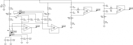
I noticed that the advertised 12db crossovers are as such only at the low ends of both the high and low pass filters, but at the upper range where I need it, it stretches out to 6db. Changing C9 in the low pass changes the roll off, so if I make it much larger, the upper range gets a nice 12db roll off as well as a little +3db bump at the top. If I align that bump with the -5db slump in the driver's response at 1200Hz, it not only makes up for the slump, but also cuts down the output precipitously before reaching the woofer's break up point at about 2200hz and up.
Looking at the high pass filter, all I need to change is R27 to a 2k to get back the 12db slope and tune the pot to about 2kohms which crosses over perfectly with my LPF.

But I would like to keep the original specs because this amp could be used in other projects, cars, etc, and I prize utility. Unfortunately, these mods favor the upper range of this project at the sacrifice of the much more common lower range. Thus, I installed a switch for changing the range between 2 different C13s and two C9s to change the slope. I don't think I'll leave the stock filters in place because the resistor changes require reconfiguring them, but I can reuse most of the original caps. For the HPF, all I need to do is install a 20k pot in place of R27.
Turning to look at phase angle, I was originally worried about the extreme change on the LPF when I created the bump up at 1200hz. Not being familiar with crossover design, I didn't realize that the HPF phase change might be in line with it. To my surprise, changing the HPF to 12db at 1700hz made it nearly a perfect match... except it's 180 degrees out. But that's perfect, right? I can just wire the tweeter backwards? I plan to double check this on the actual hardware to confirm before I go building it into the box.

When I run the output of the LPF into the ground of the HPF, I get a modeled estimate of the combined response of the actual drivers with the tweeter wired backwards. Looks exactly like I want it too, a 3db boost at 1200hz and otherwise quite flat.

And one last thing. I noticed that the op amps are marked "L074D 044" with no other designator or manufacturer logo. I'm assuming this means they're no name TL074s, but TI doesn't have a "D" model that I can see on their datasheet. I did however find Chinese knock offs on Alibaba for sale marked TL074D, so I'm pretty sure that's it. I don't want to bag on US Acoustics quality which is probably fine, but having dealt with the devastating effects of knock off chips to the tune of millions of dollars, I'm thinking I'll change them out for genuine chips. I happen to have 3 perfect little matching DIP14 TL074CNs that should be drop in replacements. In reverse engineering the schematics, everything matches up as expected to the TI layout. It's also tempting (but expensive) to change out all the 5% resistors for 1% foils. Meh, I'll just leave that alone.

I noticed that the advertised 12db crossovers are as such only at the low ends of both the high and low pass filters, but at the upper range where I need it, it stretches out to 6db. Changing C9 in the low pass changes the roll off, so if I make it much larger, the upper range gets a nice 12db roll off as well as a little +3db bump at the top. If I align that bump with the -5db slump in the driver's response at 1200Hz, it not only makes up for the slump, but also cuts down the output precipitously before reaching the woofer's break up point at about 2200hz and up.
Looking at the high pass filter, all I need to change is R27 to a 2k to get back the 12db slope and tune the pot to about 2kohms which crosses over perfectly with my LPF.

But I would like to keep the original specs because this amp could be used in other projects, cars, etc, and I prize utility. Unfortunately, these mods favor the upper range of this project at the sacrifice of the much more common lower range. Thus, I installed a switch for changing the range between 2 different C13s and two C9s to change the slope. I don't think I'll leave the stock filters in place because the resistor changes require reconfiguring them, but I can reuse most of the original caps. For the HPF, all I need to do is install a 20k pot in place of R27.
Turning to look at phase angle, I was originally worried about the extreme change on the LPF when I created the bump up at 1200hz. Not being familiar with crossover design, I didn't realize that the HPF phase change might be in line with it. To my surprise, changing the HPF to 12db at 1700hz made it nearly a perfect match... except it's 180 degrees out. But that's perfect, right? I can just wire the tweeter backwards? I plan to double check this on the actual hardware to confirm before I go building it into the box.

When I run the output of the LPF into the ground of the HPF, I get a modeled estimate of the combined response of the actual drivers with the tweeter wired backwards. Looks exactly like I want it too, a 3db boost at 1200hz and otherwise quite flat.

And one last thing. I noticed that the op amps are marked "L074D 044" with no other designator or manufacturer logo. I'm assuming this means they're no name TL074s, but TI doesn't have a "D" model that I can see on their datasheet. I did however find Chinese knock offs on Alibaba for sale marked TL074D, so I'm pretty sure that's it. I don't want to bag on US Acoustics quality which is probably fine, but having dealt with the devastating effects of knock off chips to the tune of millions of dollars, I'm thinking I'll change them out for genuine chips. I happen to have 3 perfect little matching DIP14 TL074CNs that should be drop in replacements. In reverse engineering the schematics, everything matches up as expected to the TI layout. It's also tempting (but expensive) to change out all the 5% resistors for 1% foils. Meh, I'll just leave that alone.
Last edited:
Try and get JRC made 074s, better than TI, if needed.
No maker's mark means D quality, not trustworthy.
A is original.
B is close copy, a letter missing or changed, same numbers, maker's mark is there, real maker.
C is copy, but with markings like ST, who stopped production long back, you are taking a chance there.
D is only full or partial number, may be remarked chip. No maker's mark at all. Not to be used.
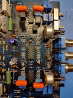
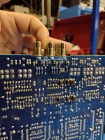
Well, I ordered parts and got it built to my specs. I replaced the "L074D" knockoffs with TL074BCN's which had an offset voltage of 2-5mV instead of the 5-8 iirc of the A version. I also replaced every resistor and cap in the filter circuits with 1% instead of 5%. I was originally going to build in switches as I had in my schematic above to make the amp more versatile, but then I thought... why? This thing is going into a permanent installation. Heck, might as well remove all the switches for that matter and wire them directly. Removed the RCAs too, no need for those (I have an aux in 3.5mm jack). I also removed the frequency pots which were knock off Bournes carbon deposit pots and replaced them with cermet trims. Soldered in a coupla test point loops to measure and set them exactly where I needed it to within 1%.
I've since removed the RCAs seen below and replaced them with direct wires from the BT module and aux input. I wired the inputs together instead of using the RCA jumpers shown in a previous post. This will help the amp fit in my case while allowing more room beside it for a small compartment for wires to move, put your phone in etc without having stuff sticking out or switches and pots to bump or play with.
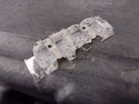
So then I assembled everything back into the chassis with thermal SIL pads instead of crummy goop and whatever sorta insulation sheet they had in there. It looked like clear plastic but broke and flaked like mica when bent.
I needed to install a bluetooth 5.1 module into it which fit nicely onto a standoff in the corner with a piece of nomex insulation under it just in case (electrolytic caps with bare tops underneath). Then I cut holes in the cover for the BT button and light as well as the 3.5mm aux input and a switch to keep them separate. I considered simply wiring the aux and BT together, but I didn't want to have an accident where both were playing at the same time and double the input, potentially blowing the drivers out.
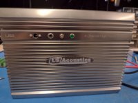
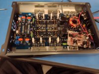
Assembled it back together and time to plug it in and test! Connected my phone to BT with a signal generating app and connected up a 2 channel scope to the outputs. I get about 2.5V difference from 500hz to a peak at just under 1200hz on the low pass exactly as planned, and the high and low pass are about 1.4x higher at passing freqs than at the 1500hz crossover where they both equal out, so that should be a perfect 3db cross point according to information I found here. The only thing wrong that I found was that my right and left outputs on the high pass are about 10% different, but that only equates to a couple db at most I think, so probably not worth taking it apart to replace the gain pots with cermet trims, but it is tempting.
I've since removed the RCAs seen below and replaced them with direct wires from the BT module and aux input. I wired the inputs together instead of using the RCA jumpers shown in a previous post. This will help the amp fit in my case while allowing more room beside it for a small compartment for wires to move, put your phone in etc without having stuff sticking out or switches and pots to bump or play with.


So then I assembled everything back into the chassis with thermal SIL pads instead of crummy goop and whatever sorta insulation sheet they had in there. It looked like clear plastic but broke and flaked like mica when bent.

I needed to install a bluetooth 5.1 module into it which fit nicely onto a standoff in the corner with a piece of nomex insulation under it just in case (electrolytic caps with bare tops underneath). Then I cut holes in the cover for the BT button and light as well as the 3.5mm aux input and a switch to keep them separate. I considered simply wiring the aux and BT together, but I didn't want to have an accident where both were playing at the same time and double the input, potentially blowing the drivers out.


Assembled it back together and time to plug it in and test! Connected my phone to BT with a signal generating app and connected up a 2 channel scope to the outputs. I get about 2.5V difference from 500hz to a peak at just under 1200hz on the low pass exactly as planned, and the high and low pass are about 1.4x higher at passing freqs than at the 1500hz crossover where they both equal out, so that should be a perfect 3db cross point according to information I found here. The only thing wrong that I found was that my right and left outputs on the high pass are about 10% different, but that only equates to a couple db at most I think, so probably not worth taking it apart to replace the gain pots with cermet trims, but it is tempting.
- Home
- Loudspeakers
- Multi-Way
- Flight case boombox project