About 6 months ago, I posted results of testing flared ports for turbulence.
The discussion ran for 6 pages in the following thread:
http://www.diyaudio.com/forums/showthread.php?s=&threadid=64528&highlight=
That work described how increasing flare size allowed a higher velocity to be used before turbulence became audible.
Since then, I've built some larger boxes and more ports, allowing me to discover where this effect "rolls off" as "core" turbulence takes hold. Additionally, I've found that port performance varies with frequency.
All the findings, along with a much improved "Flare-it" calculator can be found at the original URL:
http://www.users.bigpond.com/bcolliso/index.htm
I hope you all find it useful, and I look forward to the discussion...
regards
Collo
whoops,
that link is to the homepage
the one for the tests is:
http://www.users.bigpond.com/bcolliso/flare-testing.htm
Collo
that link is to the homepage
the one for the tests is:
http://www.users.bigpond.com/bcolliso/flare-testing.htm
Collo
Thanks Paul,
thanks for that comment.
Here's an example of how the new calculator can be used .....
In the original thread you asked:
my best answer at the time was:
"Flare-it" now provides a much better answer:
The limiting velocity for a 100mm diameter port is 29 m/sec @ 30hz, and 19 m/sec below 25hz.
To control boundary turbulence up to these velocities, a 44mm flare is required - there is no advantage in going any larger!
Regards
Collo
thanks for that comment.
Here's an example of how the new calculator can be used .....
In the original thread you asked:
Can this be right? I entered a 100mm vent with 72mm flare radius and it says 42.9m/s is ok!!!
my best answer at the time was:
There is of course the principle that the unflared section of the port also has a speed limit.
"Flare-it" now provides a much better answer:
The limiting velocity for a 100mm diameter port is 29 m/sec @ 30hz, and 19 m/sec below 25hz.
To control boundary turbulence up to these velocities, a 44mm flare is required - there is no advantage in going any larger!
Regards
Collo
Hi collo Could I have a chat with u on msn my addy is phillfyspoon@msn.com
want to talk about flares 😀
want to talk about flares 😀

hi collo
Im poor at maths could u workout what mold i need to heat mold 25mm flares on a 6inch port
Im poor at maths could u workout what mold i need to heat mold 25mm flares on a 6inch port
Cut three MDF disks to the same size as the internal diameter of the pipe. Screw the first disk to a baseboard. Screw the next disk to the first one, end then the last one to that.
I usually calculate the exact size of the disks to minimise the amount of filler required, but for a 25mm flare, the savings are minimal.
Cut a 25mm disk from whatever material you have available to use as a scraper.
I usually calculate the exact size of the disks to minimise the amount of filler required, but for a 25mm flare, the savings are minimal.
Cut a 25mm disk from whatever material you have available to use as a scraper.
The shape does matter.
Theoretically there are many profiles that can be used for a flare, however the tests I've done are all based on a circular profile.
If you were to move to something else, say for example, an exponential flare, the rate of expansion would be different.
This would need a whole new set of tests to accurately find the usable velocities.
However, the change in usable velocities would be more for large flares than smaller ones.
Since the heat flaring method is only good for flares up to 25mm, I imagine you would still get good results provided there were no sharp bends in the mould.
regards
Collo
Hi collo
I have made the full port with the bend and flares on both ends
Due to alittle miss caculation the end of the port is about 2 inches from the top of the box
will it create a problem?
I have cut all the mdf thanks to box notes 🙂 just have to glue it
I have made the full port with the bend and flares on both ends
Due to alittle miss caculation the end of the port is about 2 inches from the top of the box
will it create a problem?
I have cut all the mdf thanks to box notes 🙂 just have to glue it
I assume you are saying that the intake flare is 2 inches from the top of the cabinet.
Normally you try to leave a clearance around the port equal to the diameter of the port - in your case 6 inches.
If it is just a matter of making another front panel with the port exit 4 inches lower, I would do it.
If your port lengths are already cut, but moving the 90 degree bend further towards the back of the box could fix the problem, I would make a joiner.
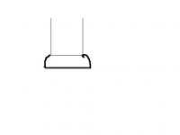
If you are truly stuck with the design, have a look at the cross-sectional area presented to the air as it flows between the flared end of the port and the box top.
on the attached drawing....
Area of flare exit shown in red = pi*r*r = pi * 4 * 4
Area of cylinder above port shown in yellow=circumference*height=2*pi*4*2
They're the same, meaning the air doesn't have to change speed as it flows around the end of the port. Not ideal, but you'll probably get away with it.
Normally you try to leave a clearance around the port equal to the diameter of the port - in your case 6 inches.
If it is just a matter of making another front panel with the port exit 4 inches lower, I would do it.
If your port lengths are already cut, but moving the 90 degree bend further towards the back of the box could fix the problem, I would make a joiner.
If you are truly stuck with the design, have a look at the cross-sectional area presented to the air as it flows between the flared end of the port and the box top.
on the attached drawing....
Area of flare exit shown in red = pi*r*r = pi * 4 * 4
Area of cylinder above port shown in yellow=circumference*height=2*pi*4*2
They're the same, meaning the air doesn't have to change speed as it flows around the end of the port. Not ideal, but you'll probably get away with it.
Attachments
I cant get away with more depth because it is about the same from the rear wall to. I will have to make the port shorter which will raise the tuning to 21hz.
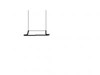
phillfyspoon said:instead of this:
haha poor drawing i know
Try borrowing a bowling ball or similar sized ball to get the flare shape.
Do you have enough room for a second 90 degree bend? Or maybe even a 45 degree bend will allow the air to be at a lower velocity combined with a diminished angle - less probablity of chuffing. If you inserted the 45 degree bend further back the port would be running at an angle within the enclosure, and therefore would have a longer line before reaching the opposite wall.
I have the wood cut now so shorting the port is only option
I point you to this thread
http://www.diyaudio.com/forums/showthread.php?s=&threadid=74944
am I right in thinking hte response is distance doesnt matter?
I point you to this thread
http://www.diyaudio.com/forums/showthread.php?s=&threadid=74944
am I right in thinking hte response is distance doesnt matter?
Am i measureing from the port or the outside of the flare?
The outside of the flare is close to a rear wall but not close if from the actual port
The outside of the flare is close to a rear wall but not close if from the actual port
you measure from the outside of the flare.
Being close to the rear wall is no great problem if you have a reasonable clearance to the sides and front wall.
Being close to the rear wall is no great problem if you have a reasonable clearance to the sides and front wall.
Sweet
Nice work. I derived some flared port equations about a year. I cant wait and compare them to your data.
Nice work. I derived some flared port equations about a year. I cant wait and compare them to your data.
- Status
- Not open for further replies.
- Home
- Loudspeakers
- Subwoofers
- Flared Ports Part 2