Hi everyone! I am new to diyaudio but have been a lurker for a while. It is a fantastic site and I love spending time reading the threads here - having found many an answer I was looking for. I greatly respect some of the renowned members here and their knowledge.
I am a new owner of a Kenwood 700c preamplifier. I have some questions about improving the circuitry in this preamp and being a novice, only have a general idea about what can be done to bring it to 2011 - maybe at least half the way from 1974.
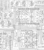
Here are the links to the schematics thanks to fotoalbumet.com:
http://www.fotoalbumet.com/u/00/24/40/files/Manuals/Model-700C_1.PNG
http://www.fotoalbumet.com/u/00/24/40/files/Manuals/Model-700C_2.PNG
I cannot seem to find any issues with the first buffer stage and the filter stage - except that the low pass filter stage has the 2.2K ohm resistor acting like a base stopper and has no resistor load at the output.
The tone control stage has no CCS. A good CCS would be an effective improvement. The Miller cap is ceramic, I will change it to a silvered mica. Feedback can be altered in this section as well, possibly eliminating global feedback. I discovered no local decoupling in the tone control board, so I will add a 100uF electrolytic and .1 uF MKP on the positive and negative rails.
The phono stage has a high working voltage, in part to give the CCS resistor a more ideal character. I cannot see anything that could be done except that the 47 pf cap on the LTP is a bit high; there is no capacitive loading of the cartridge as well.
The beauty of this preamp is that everything is modular with plenty of space to work, so I could even design PCB's with the same Amphenol connectors and swap them out without really making any disfiguring changes that would alter its original character.
I ask all members of this forum to give me advice, to confirm if the statements I made are right and possibly give me advice on how to proceed. Thank you all for your time and for helping me out 🙂
I am a new owner of a Kenwood 700c preamplifier. I have some questions about improving the circuitry in this preamp and being a novice, only have a general idea about what can be done to bring it to 2011 - maybe at least half the way from 1974.
Here are the links to the schematics thanks to fotoalbumet.com:
http://www.fotoalbumet.com/u/00/24/40/files/Manuals/Model-700C_1.PNG
http://www.fotoalbumet.com/u/00/24/40/files/Manuals/Model-700C_2.PNG
I cannot seem to find any issues with the first buffer stage and the filter stage - except that the low pass filter stage has the 2.2K ohm resistor acting like a base stopper and has no resistor load at the output.
The tone control stage has no CCS. A good CCS would be an effective improvement. The Miller cap is ceramic, I will change it to a silvered mica. Feedback can be altered in this section as well, possibly eliminating global feedback. I discovered no local decoupling in the tone control board, so I will add a 100uF electrolytic and .1 uF MKP on the positive and negative rails.
The phono stage has a high working voltage, in part to give the CCS resistor a more ideal character. I cannot see anything that could be done except that the 47 pf cap on the LTP is a bit high; there is no capacitive loading of the cartridge as well.
The beauty of this preamp is that everything is modular with plenty of space to work, so I could even design PCB's with the same Amphenol connectors and swap them out without really making any disfiguring changes that would alter its original character.
I ask all members of this forum to give me advice, to confirm if the statements I made are right and possibly give me advice on how to proceed. Thank you all for your time and for helping me out 🙂
I can't help with your audio problem, but I can give you some advice. Use a thread name which actually says what you want to know about e.g. "advice on modding Kenwood 700c preamp". That might attract people who can help.
Thanks DF96. I apologize. Do I have to let the moderators know to edit the thread name?
I re-read my previous post and realized that I was not very specific. When I wrote that there was no CCS I meant that the input LTP's in both the tone and phono stage have a simple resistor/resistors in series doing CCS duty - according to the KISS principle but my question was why not improve upon it with a discrete or IC two lead version in place of the resistor/resistors.
I'd love to hear any comments on this. Thanks in advance for your comments - I will figure out what I should do to change the name of the thread.
 Done.
Done.Hi all
Obviously I asked some questions that were way off and made totally wrong assumptions in my first post. I am still learning - my background is not EE. I apologize for the dumb questions but the really dumb ones are the ones not asked.
I now have a specific issue with the 700c. I have replaced all electrolytics with Nichicon HE caps; signal caps have been replaced with film caps where there were electrolytics due to Kenwood's cost cutting decisions in the course of manufacture - there are holes in the PCB for larger film caps so it was just a matter of returning everything back to what the original engineers intended.
I have been using it for the past 2 weeks (roughly). I did not believe in burn in at first. I am a convert now. I was actually appalled at first. The treble has slowly revealed itself now. I can hear high hats and cymbals well. Thing is, there is still one "issue". Strong non-distorted treble information lack the attack and sharpness I find in my other preamp which is a current model from Parasound. Granted, I am comparing a 40 year old preamp to SOA. But I have not heard any other, even older preamps behave like this. The treble attacks in music including SS sibilants get distorted whereas I can hear them clean and sharp with the Parasound. This happens in both channels.
Now coming to the point - I used a Nichicon HE 100 uF cap for the emitter bypass caps C17 and C18. I read about the emitter bypass Ce cap and how to determine its value.
My question is why not a higher value Ce cap to bring the cutoff frequency lower than 106 Hz?
Please correct me if I got all this wrong: the Ce value is chosen so Xc is 10% of the resistor value.
Lastly, am I right in realizing now that these caps should have been a Cerafine or Silmic with a 1 uF FKP bypass?
I may be wrong in learning some of these electronic basics, please correct me if I am wrong. When I have the time I am going to get hold of a good book. Please give me some recommendations – all replies however critical and harsh will be much appreciated 🙂
Attachments
Last edited:
It was the emitter bypass caps! The first step I took was to take the Nichicon HE's out. The improvement was not subtle. Bass warmth suffered a little but the rest of the spectrum sounded so good I was tempted to leave it that way.
I've installed 100 uF SilmicII's now, currently burning in. It already sounds a lot better than before, but not quite like how it did without any cap. I think I am close to realizing why so many hold this preamp in such high regard.
I've installed 100 uF SilmicII's now, currently burning in. It already sounds a lot better than before, but not quite like how it did without any cap. I think I am close to realizing why so many hold this preamp in such high regard.
- Status
- Not open for further replies.
- Home
- Source & Line
- Analog Line Level
- Fixing a Kenwood 700c preamplifier - help please!