I Agree It looks Like the Driver is faulty
The output of the TL should be nice Square Waves as should the Output of the driver stage.
CRO is a Cathode Ray Oscilliscope. Sorry Old people speak for oscillicope like you are using to measure waveforms
Good Luck
Brett
The output of the TL should be nice Square Waves as should the Output of the driver stage.
CRO is a Cathode Ray Oscilliscope. Sorry Old people speak for oscillicope like you are using to measure waveforms
Good Luck
Brett
Ok, parts finally came in. I replaced the drivers (KTA1266 replaced with KSA1015 and KTC3198 with KTC1815). Amp is drawing 1.3 Amps, and output relay clicks on. Nothing gets hot except the 7812 and only after a minute.
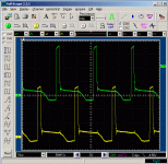
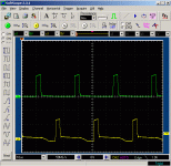
The two sets of IRFZ44N gate waveforms depicted below. With the board not attached to the heatsink, is there much danger trying a very small audio input to drive a 4ohm speaker at very low volume? The amp would be connected to a 1amp limited supply for the test.
The two sets of IRFZ44N gate waveforms depicted below. With the board not attached to the heatsink, is there much danger trying a very small audio input to drive a 4ohm speaker at very low volume? The amp would be connected to a 1amp limited supply for the test.
Attachments
I would Bolt it back on the heatsink before any more testing is done to ensure cooling is achieved.
Drivers look better, Could you measure the waveforms before the resistor to the IRF44 fets. That liitle bump at the bottom of the waveform is interesting. and the Top is not fully square, Is your Probe DC connected?
Cheers
Brett
Drivers look better, Could you measure the waveforms before the resistor to the IRF44 fets. That liitle bump at the bottom of the waveform is interesting. and the Top is not fully square, Is your Probe DC connected?
Cheers
Brett
Yes, the probes are set to DC coupling. That waveform was identical before and after the resistor to the IRF44 fets.
I wan't sure what to make of the below zero signal or the rounded tops...
I did go ahead and connect it to a speaker for a few seconds, just long enough to hear that it is outputting decent-sounding audio at very low volume.
I'm cleaning up the smoldered junk in the heatsink and replacing the heat sink compound now to bolt it back in, unless you think there may be further problems based upon the gate signal?
Thanks
Am I ready the Waveform correct that the Peak Voltage is around 8v.
Whats the DC supply voltage thats feeding the drivers and the PWM chip?
Cheers
Brett
Whats the DC supply voltage thats feeding the drivers and the PWM chip?
Cheers
Brett
Hi
I agree with brettcoupe. That is not even 8v. When testing use recomended input voltage for amp (12-14v).
Also can you check any resistor in path to gates and tell me where they are (before/after buffer....) and their value.
7-8v should be enough to fully open this fet, but I would be more happy if I would see it around 10V, coz you should have almost full voltage when gate is turned on.
1.3A? I think that whis is ok for this big amp.
DO NOT TEST it without heatsink, trust me, I have blown two 44's with only 30A
You may ask why 7-8v is not enough. Well you must consider, that this is big amp and will sag your batter voltage alot (if you don't have 300€ worth one). This means that your gate voltage will go down, maybe even that low that you will blow fets again.
In this case, I said I would be testing it with a 1amp limited supply [really it's more like 1.5amp] - nothing like 30amps... And that's sufficient for most amps I've messed with to power up and play some.
I am supplying the amp with ~13 volts, and I have a meter on the supply so I know it's not dropping, thus isn't the cause of the low gate voltage.
The supply of the TL494 is a steady 8-10volts, depending upon the supply voltage.
The supply to the Buffer transistors is = +batt
All 10 of the resistors going to the IRFZ44 gates are 100 ohm. Both before and after the resistor, on all of them, the waveform is nearly identical and look like the image I posted earlier.
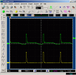
The image below is the TL494 Pin 9 output (yellow) and the corresponding buffer output (green). Note that I changed the voltage scale on this image to 5v/div.
According to the IRFZ44N datasheet, they are fully on at a maximum of 4 volts, so 7-8 volts should be plenty, even given a supply voltage drop. I'm no expert with this, but it appears to me as if they wanted to avoid fluctuations in the gate voltage...???
I hooked the amp to a car battery I keep charged for testing (after mounting it to a heatsink) and I can push it pretty hard off the battery. Battery voltage drops to about 10 volts during a hard hit. I'll post the gate voltage during a hard hit next.
It does have some high-pitch squeal being transmitted into the speaker... Normal for an el-cheapo like this? It doesn't seem to increase with volume, so I guess it's being induced into the output?
Attachments
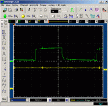
In this image you see the +batt voltage dropping to +10v with the amp turned all the way up and the input turned way up (input from a portable cd player).
The IRFZ44 gate is the green, and the yellow is the +batt voltage.
The supply is putting out 61.8 Volts. Humm, guess that means at *best* I can expect 477 watts at 4 ohms or 1909 at 1 ohm. A faaarrrrrr cry from what it's rated...
I've had it playing at low volume, and at times high for a few seconds, since I began writing the previous message. Seems odd to me, but the toroidal inductors on the output are getting warm, almost hot. Nothing else is. Normal?
Attachments
Hi,
It Looks Better
However I still think that the driver O/P should be Higher V and Cleaner on the zero V line.
Also I hope that Spike thats on teh Batt Trace and on the Green Trace is due to the Inductive Pickup of the Core into the Probe lead.
Are u able to sketch out the driver section schematic?
Cheers
Brett
I dunno what the spike is from... Didn't think too much of it.
Why do you want the sketch? I can do it, but it'll take a lot of time...
Aside: I likely won't be able to check back in here again until Monday.
Why do you want the sketch? I can do it, but it'll take a lot of time...
Aside: I likely won't be able to check back in here again until Monday.
If its too much bother dont worry
I am just concerned that the Driver is not turning off fully, and leaving a bit on after the Pulse. if you look carefully it looks Like it is up around a 1-3 volts briefly. This could cause some leakage and minor Cross over of the Fets It could also account for the Spike and it kinda co-incides for when the driver goes Off properly.
I gather this driver stage is a pair of Transistors One to + and One to GND . One Set per Side.
Thoughts?
No, it's not much trouble. I got crosswired and was thinking of something else. I'll sketch the fet drivers and post it Monday. Thanks.
Hi
I think what your problem is Batt sag, if you could keep it higher then 13v at all times, you would get more power out of it.
From pic that you posted, it looks to me that your amps duty cycle is almost 50% (D.C. + some dead time).
Output coil heating? Normal coz this is Damp, so heating of output coil is normal even at idle.
Gate turns on from 2v to 4v, but for fet to conduct large amps, it need more voltage then that.
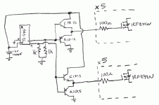
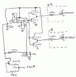
Ok, here's the driver section, from TL494 to the FETs.
My supply voltage is dropping quite a bit; at max volumes the fet driver voltage drops, but as long as the supply V doesn't drop too much, it's Ok.
I can't figure why the driver is at only ~7 volts when the supply to them is 12V. Doesn't make sense to me. The only place I see 7 volts is at the output of the TL494 before the buffer. See next post.
Edit: I forgot to rotate the PIC.
Attachments
Hi
7v before buffer is more than enough to open those transistors fully. Did you already replace those?
7v before buffer is more than enough to open those transistors fully. Did you already replace those?
Hi
I really don't see how this is possible. TL has input drivers, that now drive buffers. Is there on E or C any resistor before it? Like from Vcc to C, E goes then to buffers....
I really don't see how this is possible. TL has input drivers, that now drive buffers. Is there on E or C any resistor before it? Like from Vcc to C, E goes then to buffers....
You mean that the collectors of the NPN buffer transistors are using Pin 8 of the TL494 for their source of current?
If so, I thought that was really odd too. There is NO other trace I can find that connects to the NPN collectors except two which I can't see how they would be a supply line:
1 - crosses the board and goes to a 10k resistor, which because of a few things I figure must be part of the protect circuit.
2 - goes to the anode of a small signal diode
That's it. I have NO IDEA where the +12 is coming from, unless it's coming from Pin 8 of the TL494.
Edit: I just found that I missed a connection below the TL494 chip. Pin 8 also connects to Pin 11, which then goes to a transistor. I will post an updated sketch shortly...
- Status
- Not open for further replies.
- Home
- Amplifiers
- Class D
- Fixing a BOSS REV3000D amp
