Hey, I was looking into making a self bias using a CCS for an EL34 amp, but I just found a 24v transformer that I ripped out of an iced tea machine (the fruits of dumpster diving), and I noticed that after being rectified, its just around the right voltage for a fixed bias on an EL34.
I wanted to know what the advantages, and dis-advantages of a fixed bias? or will this iced-tea machine transfomer (SEC: 24v, 2 amps) not work?
I wanted to know what the advantages, and dis-advantages of a fixed bias? or will this iced-tea machine transfomer (SEC: 24v, 2 amps) not work?
I'm going to tag along in this topic if alex don't mind.
Fixed bias on SET- what are the advantages and disadvantages?
Fixed bias on SET- what are the advantages and disadvantages?
At first, no more #$£%§* cathode bypass cap 😀
The better bypass is a short straight piece of wire
Yves.
The better bypass is a short straight piece of wire
Yves.
Hi Yves, yes no more BlackGate or whatever flavor of the month for the bypass, lower B+ too, but what about the sound?
Good point ArnoldC. The sound is different. With some tubes in some setups i prefer fixed bias with its better bass and dynamics while in others it becomes too harsh.
With enough effort and tweaking both biasing schemes can be made to sound great.
And btw the voltage for fixed bias needs to be very, very clean - you can hear every component of the biasing network.
With enough effort and tweaking both biasing schemes can be made to sound great.
And btw the voltage for fixed bias needs to be very, very clean - you can hear every component of the biasing network.
Agreed.
I beleive that the impedance and the speed of the B+ source also plays a great role.
Some "drawback" in it - more or less hidden in auto bias - may be "revealed" with fixed bias.
"Beans counters compromises" other says "Good engineering practices" 🙄
Yves.
I beleive that the impedance and the speed of the B+ source also plays a great role.
Some "drawback" in it - more or less hidden in auto bias - may be "revealed" with fixed bias.
"Beans counters compromises" other says "Good engineering practices" 🙄
Yves.
alexmoose said:Hey, I was looking into making a self bias using a CCS for an EL34 amp, but I just found a 24v transformer that I ripped out of an iced tea machine (the fruits of dumpster diving), and I noticed that after being rectified, its just around the right voltage for a fixed bias on an EL34.
I wanted to know what the advantages, and dis-advantages of a fixed bias? or will this iced-tea machine transfomer (SEC: 24v, 2 amps) not work?
The advantage of fixed bias is almost always lower THD. If you derive that fixed bias from a negative rail and a DC coupled cathode follower, you also get much improved transient overdrive behaviour. The main problem with cathode bias is that a transient overdrive that increases the current also increases the bias and pushes the operation into a more nonlinear portion of the loadline. This distortion can persist until that extra voltage leaks off. This will degrade the sound.
The main disadvantages is the need for a negative rail (really NBD with solid state diodes in the main PS) and that it is not a "set it and forget it" proposition. You will need to keep an eye on current balance periodically and adjust as required. It is also less forgiving of inherent tube mismatch, and will always require touch up if changing tubes.
Regardless, I much prefer fixed bias.
guys, I'm looking at some schematics of Antique Sound Labs fixed bias 2A3, 300B amps and their bias circuit is sooooo simple- just a diode, a cap and a couple of resistors.
What will make a good bias circuit? Regulated Tube or MOSFET or whatever?
What will make a good bias circuit? Regulated Tube or MOSFET or whatever?
I've not played around with SE enough to be able to offer an informed opinion.
But, under static conditions; fixed bias seems to offer
- less measurable distortion
- more efficiency (less heat wasted)
- the opportunity to finally remove that darned sonically-deleterious bypass cap
However...
- It's also been stated that fixed bias takes longer to recover from overload, and that this is one reason why cathode-bias is purported to sound better, even despite the now missing bypass-cap. For more on this see: "The Fixed-Bias Story" by Herbert Ravenswood, February 1958, Radio-Electronics magazine, pages 47-49. (ask me if you need a PDF copy)
As with all things, YMMV.
My suspiscion is that some amps in some settings will sound better to some listeners, and others won't.
arnoldc said:guys, I'm looking at some schematics of Antique Sound Labs fixed bias 2A3, 300B amps and their bias circuit is sooooo simple- just a diode, a cap and a couple of resistors.
What will make a good bias circuit? Regulated Tube or MOSFET or whatever?
Primarly, a lo R and Z one.
Use at least a decent bleeder.
Majestic : An hi R or Z bias source ceratainly does not help for fast recovery from an overload !
Serie regulators are the worst in this situation cos they can't "suck" the grid current.
Shunt ones had my preference.
Be aware to DO NOT regulate the bias voltage without stabilizing plate voltage too. Not so easy to do.
With tetrodes or penthodes, just the screens need to be regulated.
Consider also simply changing the existing cathode resistor for a voltage source like zener or led chain 😉 As SY says !
Yves.
I'm just pointing out what else has been said on the subject.Yvesm said:
Majestic : An hi R or Z bias source ceratainly does not help for fast recovery from an overload !
I've temporarily uploaded a link to the article I cited above. (will remain valid for the next 7 days)
Thanks for the file!
I haven't read the entire SP article yet, but I'm seeing discussions for push-pull.
How about SET? 😉
I guess I have to find out for myself
I haven't read the entire SP article yet, but I'm seeing discussions for push-pull.
How about SET? 😉
I guess I have to find out for myself
arnoldc said:guys, I'm looking at some schematics of Antique Sound Labs fixed bias 2A3, 300B amps and their bias circuit is sooooo simple- just a diode, a cap and a couple of resistors.
What will make a good bias circuit? Regulated Tube or MOSFET or whatever?
Yup. And don't tell me these amps sound amazing 🙂
Whatever PS would sound the least objectionable to you should do the trick. Chokes, nice caps, multiple stages filtration and softer sounding diodes are all very helpful. Tube rectification is sadly out due to potential drift, slow warm-up and other non-audio related ills.
I once decided to get rid of the fixed biasing arrangemet on my old ST70. It uses a selenium cell which is notoriously unreliable and generally a bad idea. A MUR860 went in place of the cell and i also replaced the smoothing caps with Cerafines.
The sound became unbearably bright and tiring. Even with the original caps the MUR860 showed too much personality. It may have been just a question of break-in but the original selenium supply simply fitted better the relaxed low res sound of the ST70.
Yvesm said:
Some "drawback" in it - more or less hidden in auto bias - may be "revealed" with fixed bias.
With you 100% on that one. Another advantage when using tubes with low drive requirements like the EL84 (sorry arnold, no 2A3s allowed 😉) is the possibility using the OPT secondary as the cathode load to derive a little local stage feedback.
Consider also simply changing the existing cathode resistor for a voltage source like zener or led chain As SY says !
I'm not so sure on that one. Fixed is fixed and without employing other methods to deal variations in line voltage, and hence B+, I don't see how LED cathode biasing is any less vulnerable.
I've used both fixed and cathode bias in SE amplifiers, and I much prefer fixed bias. Not only does it eliminate the colorations of a large cathode bypass cap, it generally results in much more predictable behavior at low frequencies with typical speaker loads, and subjectively much better control in the low bass.
The amplifiers I have built that use fixed bias, but are generally otherwise similar seem to have more resolution, and speed. They are less polite, and I think more musically honest. Cathode bias to me usually sounds a bit more "romantic" and forgiving on flawed program material.
Fixed bias recovery from overload can be much quicker too if this is made to be a design goal.
If you regulate the bias you must also regulate the plate supply when using triodes. With tetrodes or pentodes you may regulate just the screen supply - that said I prefer to regulate everything.
Another aspect of using fixed bias is if you make both the plate supply and the bias supply adjustable over a reasonable, but limited range you have the freedom to try different operating points which can make a big difference in your level of satisfaction with the sound.
I spent weeks fiddling around the this in my first 45 amplifier, and the conditions calculated based on my target loadline did result in the most power @ a given thd%, but interestingly not the best sound. I ended up at both a lower plate voltage and current than I originally contemplated.
As noted in another post you may periodically have to touch up the bias, but I find with the JJ300B in my main amp and vintage 45's I use in the other amplifier touching up the bias seems to be only required at tube replacement time. (After initial setting and burn-in)
Edit:
Amplifiers using unregulated supplies and fixed bias can be designed with some care to track variations in the line voltage well enough that this is a non concern. (Citation II, Marantz 8B, Dyna ST-70, MKII/MKIII/MKIV/MKVI, Mac MC30 - MC275 just a few examples.) My unregulated PP 300B amps used fixed bias and tracked well over a +/-10% variation in AC line voltage. (A few % variation)
As always YMMV..
Excuse my ignorance, I'm still a neeby in the tube world. I mostly build other people design. Here one of my current project schematic. It is an headphone amp based on EL84. I guest the bypass cap you're talking about is C2 in this schematic. I saw in some other design a battery used to establish a fixed biais, using a long life lithium battery.
1) Is a battery a good way to implement fixed bias?
2) How can I implement in this particular schematic a fixed bias?
Thanks in advance for any help you can provide 🙂
1) Is a battery a good way to implement fixed bias?
2) How can I implement in this particular schematic a fixed bias?
Thanks in advance for any help you can provide 🙂
Attachments
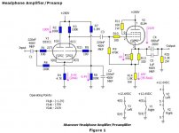
Algar_emi said:Excuse my ignorance, I'm still a neeby in the tube world. I mostly build other people design. Here one of my current project schematic. It is an headphone amp based on EL84. I guest the bypass cap you're talking about is C2 in this schematic. I saw in some other design a battery used to establish a fixed biais, using a long life lithium battery.
1) Is a battery a good way to implement fixed bias?
2) How can I implement in this particular schematic a fixed bias?
Thanks in advance for any help you can provide 🙂
Hi,
What you show is an Headphone amp or a line preamp while we are chatting about bias method for a power stage.
Here the "power" (very lo power indeed) stage is cathode loaded and uses cathode bias (also know as autobias).
As is, this schemo is not prone to bias method changing.
The cap C2 is here to clamp the AC grid voltage of the second triode to the ground while it is cathode driven by the first one.
At this place, the requirements for this cap are more relaxed than in the cathode of a power stage where AC current reaches much higher values.
Yves.
An excellent question given your requirments here.arnoldc said:Thanks for the file!
I haven't read the entire SP article yet, but I'm seeing discussions for push-pull.
How about SET? 😉
The short answer as I said before is, I just don't know in this case. So yes, given the low parts cost of both options, try each and report back! 🙂
Oh, and if I recall (need to read my own citation again -- lol) the presence of a feedback loop in an amp was a key part of the fixed bias' bad-behaviour. -- Something that also mightn't apply to all SE designs.
@ kevinkr : Thank for your comments. Some good stuff for me to think about in there too.
1) Is a battery a good way to implement fixed bias?
Did anyone try this / any theoretical thoughts? People seem to like fixed bias and battery bias so why not combine them? Easy fix for driver stages needing little bias voltage...
Cheers,
Simon
I used this simple design for a single ended amp. The transformer is just a 117/5V common unit, connected in reverse to a 6.3v filament winding. This supplies the raw voltage, which was then adjusted with appropriate resistors and pots to get the desired voltage and impedence at the grids. In the final supply, I separated the channels by duplicating the final RC section, one to each channel. Very quiet - no ripple noise whatsoever.
Sheldon
http://www.diyaudio.com/forums/attachment.php?s=&postid=823848&stamp=1137952870
Sheldon
http://www.diyaudio.com/forums/attachment.php?s=&postid=823848&stamp=1137952870

- Status
- Not open for further replies.
- Home
- Amplifiers
- Tubes / Valves
- Fixed Bias: the ups and downs