Hello,
I am currently working on an amp that uses a fixed bias supply with a source follower direct coupled to the output tube in a single ended design. The bias supply is shared by both sides of the amplifier.
I originally derived the negative bias voltage from the main B+ winding with reversed diodes, but I noticed that there was a slight hum and I didn't like the amount of heat generated in the large dropping resistor so I instead used a small transformer that i had handy that provides 200VAC/100mA.
When I set everything up, I was happy to notice that the hum was gone however, one of the output tubes was severely over-biased. With the driver and output tubes removed, I rechecked the bias supply and sure enough, instead of the maximum negative -100VDC bias I was reading around -50VDC on one side. Thinking that the mosfet was likely blown, I replaced it, only to then have the other side start also dropping voltage. OK, with both mosfets replaced, I put the tubes back in their sockets and after the warm up-- grrrrr a very loud buzzing sound.
With the tubes removed, I added first protection zeners (which I had forgotten at first) which didn't help. I then added a small break out resistor on the source of the mosfet. This seems to be beneficial for the life of the mosfets as they aren't dying now, however, the drain voltage has now started drooping into negative voltages. I am perplexed as to how this is happening.
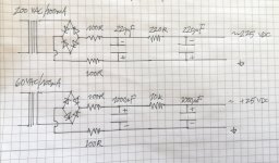
I have made some small sketches of the schematics in question (sorry for the hand drawn aspect!) Is there something in what I have done that is obviously wrong? Surely I am missing something here...
I am currently working on an amp that uses a fixed bias supply with a source follower direct coupled to the output tube in a single ended design. The bias supply is shared by both sides of the amplifier.
I originally derived the negative bias voltage from the main B+ winding with reversed diodes, but I noticed that there was a slight hum and I didn't like the amount of heat generated in the large dropping resistor so I instead used a small transformer that i had handy that provides 200VAC/100mA.
When I set everything up, I was happy to notice that the hum was gone however, one of the output tubes was severely over-biased. With the driver and output tubes removed, I rechecked the bias supply and sure enough, instead of the maximum negative -100VDC bias I was reading around -50VDC on one side. Thinking that the mosfet was likely blown, I replaced it, only to then have the other side start also dropping voltage. OK, with both mosfets replaced, I put the tubes back in their sockets and after the warm up-- grrrrr a very loud buzzing sound.
With the tubes removed, I added first protection zeners (which I had forgotten at first) which didn't help. I then added a small break out resistor on the source of the mosfet. This seems to be beneficial for the life of the mosfets as they aren't dying now, however, the drain voltage has now started drooping into negative voltages. I am perplexed as to how this is happening.
I have made some small sketches of the schematics in question (sorry for the hand drawn aspect!) Is there something in what I have done that is obviously wrong? Surely I am missing something here...
Make your bias supply adjustable,also you can fit a LPF on the gates of the mosfets to reduce hum,Hard to know what happening exacltly as you forgot to attach a schematic.
Andy.
Andy.
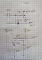
Transistor Followers can oscillate if the is no short-path decoupling of the Drain (+) supply voltage.
A 100-220nF capacitor of stacked-construction (no cyclindrical types!) should be connected directly at the drain of the FET, and to a 0V supply local to the follower, preferably a wide strip, 50mm or more wide. The bias cap should connect to the same 0V position, and the negative supply should have a similar cap, and be connected here also.
Sometime a 47-100µF electrolytic is also needed, if the supply is far from the follower.
The rest of the circuit looks good. But 100Ω as a gate stopper is better against oscillation than 1k; and 100Ω (total) in the source is usually enough.
Ah, I see, that is interesting. I assumed somehow that bigger is better when it comes to stoppers.
In terms of the "50mm wide" strip for 0V, that of course assumes a PCB. I am using a 1,5mm bus bar that runs along the circuitry and is connected through chassis ground via a 22r resistor.
The power supply itself is indeed external.
I will try to add some decoupling tomorrow and will report back.
Thank you for your help!
hmm... I am stumped.
Installing the various capacitors-- one 100n ceramic cap right on the the drains, plus a 100uF for each drain supply, as well as a 10uF and 100n at the negative supplies-- has brought nothing. The voltage at the drain starts at around -18VDC at turn on and starts going progressively more negative.
I installed a 1n4004 diode from the output of the power supply but it still goes negative as if the diode weren't there.
However, when I use my regulated bench supply, there is no issue-- the voltage stays at +25VDC.
That would appear to implicate the power supply rather than the follower circuit but without a load on the +25V supply everything is fine if naturally a bit higher than +25V.
Would it make sense to simply regulate this supply?
I simulated your circuit in LTSpice. I think that the 10k resistor in the positive supply is too large. A value closer to 1k would be better.
A thousand thanks!
That worked much much better, the value ended up being 1k6
Some day, I should learn how to use computers for something other than email!
That worked much much better, the value ended up being 1k6
Some day, I should learn how to use computers for something other than email!
- Home
- Amplifiers
- Tubes / Valves
- Fixed bias supply with DC coupled follower