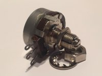
This is a practical question🙂 The potentiometer that I am using in a fixed bias supply is very "touchy", that is to say it requires a lot of fiddling and patience to get the value needed. I am worried that it may go out of adjustment as very little effort is required to turn the wiper🙁 I am sure I have seen pots that have a nut that locks the shaft but can't seem to find any on Mouser🙁 Alternatively I have read that Loctite 425 can prevent rotation but the resistance can be broken with moderate effort, only problem is that it is expensive🙁 Any ideas or help would be greatly appreciated🙂
If your control is that touchy it's probably no good or needs a good cleaning. I always use either Clarostat, AB or Ohmite 2 watt carbon pots. They're not cheap but years ago I bought hundreds surplus at hamfests or other surplus outlets. But you can still get them on eBay. And with these quality controls you don't really need the locking feature. I also dislike the little multi or single turn trim pots that so many here use.
Attachments
Last edited:
Not defective
It takes less than one turn to go from 0 to 25kohms, so of necessity small adjustments result in large changes🙁 But it was what was in the parts box so I used them. If I had thought it through I should have gone for a multiturn pot but hindsight is 20:20. Thanks for the suggestion🙂
It takes less than one turn to go from 0 to 25kohms, so of necessity small adjustments result in large changes🙁 But it was what was in the parts box so I used them. If I had thought it through I should have gone for a multiturn pot but hindsight is 20:20. Thanks for the suggestion🙂
You can add resistance between the outer lugs of the pot and what they connect to now to get a finer adjustment.
What value
Would you recommend for a 25k pot? Keeping in mind that the total value should not exceed 50k, and preferably less🙂
Would you recommend for a 25k pot? Keeping in mind that the total value should not exceed 50k, and preferably less🙂
Not aware of any way of doing so
But it is simple. Separate 60 volt transformer, then full wave bridge, capacitor, resistor, capacitor. The C- goes to the top of the pot, the other end to ground, and the wiper goes to the grid of the output tube through the secondary winding of an interstage transformer😀 It works just fine but I am worried that it can easily be mis-adjusted. Probably Audiophilia nervosa. I have found some high quality locking pots on ebay, and as usual postage is twice the value of the items I want, and will likely take a month to get here😉
But it is simple. Separate 60 volt transformer, then full wave bridge, capacitor, resistor, capacitor. The C- goes to the top of the pot, the other end to ground, and the wiper goes to the grid of the output tube through the secondary winding of an interstage transformer😀 It works just fine but I am worried that it can easily be mis-adjusted. Probably Audiophilia nervosa. I have found some high quality locking pots on ebay, and as usual postage is twice the value of the items I want, and will likely take a month to get here😉
Not attempting
It works just fine. For a 300B at 388 volts on the plate I adjust to 70ma, the max recommended current value. The B+ didn't quite get to the 400 volts I was shooting for😉 It uses a voltage regulator circuit for the filament, and the negative side is connected to ground via a 100 ohm resistor. I simply adjust the pot until the voltage across the resistor is 7 volts😎
It works just fine. For a 300B at 388 volts on the plate I adjust to 70ma, the max recommended current value. The B+ didn't quite get to the 400 volts I was shooting for😉 It uses a voltage regulator circuit for the filament, and the negative side is connected to ground via a 100 ohm resistor. I simply adjust the pot until the voltage across the resistor is 7 volts😎
What is the negative bias voltage you are aiming for?
100 ohms from filament to ground is waaaaay too much resistance unless you have it bypassed by a big cap.
100 ohms from filament to ground is waaaaay too much resistance unless you have it bypassed by a big cap.
no offense
but this method was recommended by Eli Duttman, I think it has something to do with helping to prevent runaway of the tube in the event of bias supply failure😱 The thinking being that such a value was sufficient without requiring a bypass cap, which would sort of defeat the purpose of fixed bias😉
but this method was recommended by Eli Duttman, I think it has something to do with helping to prevent runaway of the tube in the event of bias supply failure😱 The thinking being that such a value was sufficient without requiring a bypass cap, which would sort of defeat the purpose of fixed bias😉
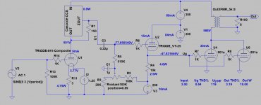
Here is a primer on the subject. If your pot is of unsuitable resistance you can double up with say 2x 22K from both ends to the wiper and another two to keep the bias out of the danger zone. There is little calculus involved.
Attachments
Last edited:
Not sure
what the image has to do with the price of fish😕 I looked at your link, lost me when he was so dismissive of tube rectifiers
what the image has to do with the price of fish😕 I looked at your link, lost me when he was so dismissive of tube rectifiers
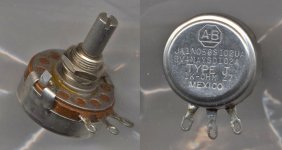
FWIW I use these for bias control.
BOCHEN(Chengdu Guosheng Tech)|BOCHEN(Chengdu Guosheng Tech) WXD3-12-2W 22K|Potentiometers & Variable Resistors|LCSC
BOCHEN(Chengdu Guosheng Tech)|BOCHEN(Chengdu Guosheng Tech) WXD3-12-2W 22K|Potentiometers & Variable Resistors|LCSC
what the image has to do with the price of fish😕 I looked at your link, lost me when he was so dismissive of tube rectifiers
If you just have the pot across the entire negative rail, you will be able to adjust from 0V of bias all the way to whatever the maximum negative voltage available from your B- supply is. That's why it seems so tweaky and sensitive to you.
The solution is in that article. There's nothing wrong with dismissing tube rectifiers.
Changes made
to the bias circuit, basically followed the schematic given in the link from painted's post. Put a 2k7 resistor from c- to the pot, connected the wiper to ground and took the -ive supply from the junction of the pot and the 2k7 resistor. Seems to work well and not nearly as touchy as before😀 I don't get what the image in painted's post was supposed to be about😕
I have built several amps that use tube rectifiers and even if I say so myself they sound pretty damned good😉
When using 100R instead of 1R or 10R for current reading the thought arises your voltage measurement contraption might be not so sensitive 😀I don't get what the image in painted's post was supposed to be about
- Home
- Amplifiers
- Tubes / Valves
- Fixed bias potentiometer