Hello clever people,
I am looking at replacing some old caps in a vintage ARC preamp (still trying to loose a tiny residual hum) and thought I might see if the output caps coming from the cathode follower on the last valve might be part of the problem. This valve has an AC heater.
Anyway the question is related to the value of these. They are currently 10 uF and I have been told by a friend that if I have a high input impedance Power amplifier (which I do at 100K) then I could happily use 1 uF and they would probably sound better, and I could afford to fit in some more exotic caps too.
Is there a calculation that manages this relationship in any way? I found a website that calculated Impedance at frequency, based on capacitance; and obviously this changes at frequency, and also implies the lower value capacitor would seem to decrease the output at lower frequencies.
Any helpful knowledge here.
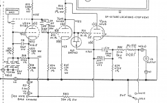
Circuit diagram attached.
Thanks!
I am looking at replacing some old caps in a vintage ARC preamp (still trying to loose a tiny residual hum) and thought I might see if the output caps coming from the cathode follower on the last valve might be part of the problem. This valve has an AC heater.
Anyway the question is related to the value of these. They are currently 10 uF and I have been told by a friend that if I have a high input impedance Power amplifier (which I do at 100K) then I could happily use 1 uF and they would probably sound better, and I could afford to fit in some more exotic caps too.
Is there a calculation that manages this relationship in any way? I found a website that calculated Impedance at frequency, based on capacitance; and obviously this changes at frequency, and also implies the lower value capacitor would seem to decrease the output at lower frequencies.
Any helpful knowledge here.
Circuit diagram attached.
Thanks!
Attachments
It is the basic equation for a high pass filter. Fc = 1 / 2*pi*RC, where R is the input impedance of your amp and C is the value of C10.
And yes, 1.0 uF or 2.2 uF will work. Polypropylene or polycarbonate film cap will sound best.
And yes, 1.0 uF or 2.2 uF will work. Polypropylene or polycarbonate film cap will sound best.
Your friend is right. This capacitor forms a 1st order high pass filter with the load resistor. With a load of 100 k, the resulting high pass will have a 1.9 Hz corner frequency (frequency at which the output signal has fallen by 3 dB). With such a low corner frequency, the attenuation at 20 Hz will be already extremely small.
The formula is: fg=1/(2*pi*R*C)
With the 475 k resistor after the cap to ground, this resistor is parallel to the 100 k input resistance of the power amp resulting in an effective load of ~ 82k leading to the 1.9 Hz corner frequency with a 1 µF cap
The formula is: fg=1/(2*pi*R*C)
With the 475 k resistor after the cap to ground, this resistor is parallel to the 100 k input resistance of the power amp resulting in an effective load of ~ 82k leading to the 1.9 Hz corner frequency with a 1 µF cap
A 0.68uF cap and 100k load will have a corner freq. of 2.6hz !
Too large cap will / may have side effects, s.a. leakage, thumps at power off/on etc.
Too large cap will / may have side effects, s.a. leakage, thumps at power off/on etc.
This is great 1 uF it is then 🙂
this will not reduce my low frequency output to the amplifier I assume, that's way too low
this will not reduce my low frequency output to the amplifier I assume, that's way too low
could I even get away with something smaller = 0.47 uF or is that a little too low do you think?
(also any idea why the input goes through a 0.47 UF collection of caps [C47,C44,C7] rather than just straight into V4?)
(also any idea why the input goes through a 0.47 UF collection of caps [C47,C44,C7] rather than just straight into V4?)
.47 µF will result in a ~ 4 Hz corner frequency - still not really critical but already starts affecting 20 Hz
For the input caps, there is some DC bias of the grid of V4, therefore some DC decoupling is needed. A direct coupling would spoil this biasing. An d why 3 caps in parallel? - they believe that it sounds better than one cap. That's quite typical for ARC - they very often parallel components.
For the input caps, there is some DC bias of the grid of V4, therefore some DC decoupling is needed. A direct coupling would spoil this biasing. An d why 3 caps in parallel? - they believe that it sounds better than one cap. That's quite typical for ARC - they very often parallel components.
thanks so much.
best stick with 1 uF then I guess, not that I get much at 20 Hz realistically though!! even with a sub
best stick with 1 uF then I guess, not that I get much at 20 Hz realistically though!! even with a sub
I could happily use 1 uF and they would probably sound better, and I could afford to fit in some more exotic caps too.
One of my friends told that yellow capacitors sound best😉.
well, I can only assume these guys have found orangey/brown to be a bit better - based on their pricing!!
Duelund Coherent Audio – Manufacturers of loudspeakers, cables and power filters. Denmark.
Duelund Coherent Audio – Manufacturers of loudspeakers, cables and power filters. Denmark.
.47 µF will result in a ~ 4 Hz corner frequency - still not really critical but already starts affecting 20 Hz
For the input caps, there is some DC bias of the grid of V4, therefore some DC decoupling is needed. A direct coupling would spoil this biasing. An d why 3 caps in parallel? - they believe that it sounds better than one cap. That's quite typical for ARC - they very often parallel components.
So a mate of mine is going to swap out his 0.22 uF coupling caps on a single ended Yoshiba 50 amp to improve the sound quality.
I have some spare 0.47 uF paper in oil caps that he would like to try and my guess is that this will not cause a problem to jump from 0.22 to 0.47.
I think from looking at the underside of the amp which I don't know the circuit of that there is a grid to ground resistor of 330K going into the grid of the 211 so my maths from the helpful earlier posts suggests that the corner frequency with 0.22 uF is 2 Hz so with 0.47 uF is 1 Hz, so not a problem?
Thoughts?
Your friend is right. This capacitor forms a 1st order high pass filter with the load resistor. With a load of 100 k, the resulting high pass will have a 1.9 Hz corner frequency (frequency at which the output signal has fallen by 3 dB). With such a low corner frequency, the attenuation at 20 Hz will be already extremely small.
The formula is: fg=1/(2*pi*R*C)
With the 475 k resistor after the cap to ground, this resistor is parallel to the 100 k input resistance of the power amp resulting in an effective load of ~ 82k leading to the 1.9 Hz corner frequency with a 1 µF cap
So for a friends amplifier - https://www.monoandstereo.com/2014/06/yoshiba-audio-50-tube-amplifier-new.html a 50 valve being driven by a 6CG7 valve.
I can see the output from the 67G7 going via a 0.22 uF cap to the grid of 50 and the resistor to ground is 330k see images.
If the cap is changed to .47 uF (as I have some to try) then the corner frequency goes from 2 Hz to 1 Hz by my simple calculation - is this ok do you think?
Thanks for all the guidance
Attachments

Merlin, the Valve Wizard makes a convincing case in his hifi preamp book for using large caps on the output, but I haven't tried larger than about 1uF. The larger you go, the more essential it is to mitigate turn on/off thumps, either with back to back Zeners or with relay muting.
I was also told that smaller caps actually sound better, and of course they cost less and are smaller.
Most of the exotic caps will not fit, and with a 1 uF for my own pre-map I get a small choice, with 10 uF I can forget any paper+Oil variants 🙂
For my friends I am going to take a chance with the 0.47 uF and see what it sounds like.
Great!
Thanks for all the advice
Most of the exotic caps will not fit, and with a 1 uF for my own pre-map I get a small choice, with 10 uF I can forget any paper+Oil variants 🙂
For my friends I am going to take a chance with the 0.47 uF and see what it sounds like.
Great!
Thanks for all the advice
- Home
- Amplifiers
- Tubes / Valves
- Fixed bias cathode follower series capacitor value?