LOL so it is quite common when you look for it..
Thanks so much for the information...It would be interesting to read the reason they did this... 🙂
Regards
M. Gregg
A quote from WAD:
"These amps share a common circuit using a compound arrangement of both fixed grid and cathode bias. Fixed bias alone offers lower distortion and better efficiency than cathode bias but needs careful adjustment to suit the individual valves used. Cathode bias offers the advantage of not needing adjustment as long as the valves are reasonably well matched (10% current). By using a mix of both arrangements WAD have a self adjusting bias but with improved distortion and efficiency compared to using cathode bias alone. This arrangement is set at approx 50/50% fixed/cathode and can be adjusted by changing either bias source but when adjusting it should be remembered to keep a good portion of cathode bias to maintain the automatic balance of the stage.
Making the Adjustment
Change the fixed portion at the potential divider R3/5 (R3/4 KEL80) or the cathode portion via the cathode resistor value.
Fixed portion
Changing the negative voltage to the grid will cause a similar change in positive voltage at the cathode. For example, making the grid more negative by 2v will make the cathode less positive by 2v. Overall bias stays the same. When current flowing through the valve is found by dividing the cathode voltage by the cathode resistor value it can be seen there is a reduction. Hence lower plate dissipation.
Cathode portion
The current flowing through the valve is partly governed by the value of the cathode resistor and found by dividing the cathode voltage by the cathode resistor. Changing the value of the cathode resistor and putting this value into the formula suggests it would be easy to calculate the new value required. However, changing the cathode resistor value does 3 other things. It changes HT voltage, cathode voltage (but not grid voltage) and overall bias. None of these matter particularly in small amounts but it does mean the cathode value has to be changed by a different amount than first thought, then checked in circuit.
Actual Settings
No harm will be caused by going from a higher to a lower plate dissipation setting and cooler running and longer valve life will result. The following values were checked in KiT88 on 240v mains with Svetlana and GE 6550 valves. Some makes of KT88/6550 valves will be happy on any of these settings but some will not... (unquote)
Thank's so much for the information,
I could not find the information for the KEL34...I guess its always the same you can find everything except the info you want..LOL
Regards
M. Gregg
Hi,
It can be done and has been done (others gave examples), however I personally would say that this kind of design combines all the disadvantages of either method and non of the advantages...
Fixed bias allows the Cathode RC combo to be dispensed with and allows higher power from a given tube, but the bias is not very stable.
Having only a small percentage (maybe 10 - 20%) of the bias in the cathode resistor does not make for a stable bias and it still requires a capacitive bypass.
I would say that I cannot really think of any good reason to use this kind of circuit whatsoever.
Ciao T
Is it possible to fix bias an output tube close to bias point and then autobias it to the correct value? So you have fixed bias not adjustable and its auto biased into correct operation?
It can be done and has been done (others gave examples), however I personally would say that this kind of design combines all the disadvantages of either method and non of the advantages...
Fixed bias allows the Cathode RC combo to be dispensed with and allows higher power from a given tube, but the bias is not very stable.
Having only a small percentage (maybe 10 - 20%) of the bias in the cathode resistor does not make for a stable bias and it still requires a capacitive bypass.
I would say that I cannot really think of any good reason to use this kind of circuit whatsoever.
Ciao T
Thank's so much for the information,
I could not find the information for the KEL34...I guess its always the same you can find everything except the info you want..LOL
Regards
M. Gregg
Attachments
Last edited:
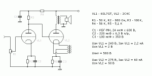
No, it's wrong. The name of this radio is EKL-34 (not KEL) !
There were many old pre-war radios using this type of biasing.
There were many old pre-war radios using this type of biasing.
Last edited:
Hi,
It can be done and has been done (others gave examples), however I personally would say that this kind of design combines all the disadvantages of either method and non of the advantages...
Fixed bias allows the Cathode RC combo to be dispensed with and allows higher power from a given tube, but the bias is not very stable.
Having only a small percentage (maybe 10 - 20%) of the bias in the cathode resistor does not make for a stable bias and it still requires a capacitive bypass.
I would say that I cannot really think of any good reason to use this kind of circuit whatsoever.
Ciao T
Here is a reason<<< If a customer said I don't want fixed bias ...I do want max power... I dont want sand in the amp what would you do?
(Give up and walk away)
I like experimenting..I'll try anything to learn..if it dosen't work then OK...
It appears to increase OTL Cathode bias from 5W to 14W OP .... 🙂
Servo is the way to go maybe...but I am not a fan of OP amps and heat..
I spent many happy hours (not) setting 8 EL34 fixed bias and waiting an hour and then a fine tune.... Then changing to KT66 do it all again...change to 6L6 do it all again...
checking again in a few weeks just to make sure its ok...then seeing a slight change in the amp... out comes the meter and away we go again...
There must be a better way.... there is...LOL
Regards
M. Gregg
There must be a better way.... there is...LOL
Indeed there is. Electronic autobias, which has been implemented analog and digital.
Hi,
I would tell him that he is issuing conflicting requirements.
If we do not apply some form of fixed bias power output must suffer, no matter what. You can of course implement a servo bias using tubes. There are also commercial solutions for DIY implementation that offer some form servo or other automagcially adjusted fixed bias.
Autobias or mixed bias will not improve the situation but make it worse. But at least you will not know about it... 😉
Ciao T
Here is a reason<<< If a customer said I don't want fixed bias ...I do want max power... I dont want sand in the amp what would you do?
I would tell him that he is issuing conflicting requirements.
If we do not apply some form of fixed bias power output must suffer, no matter what. You can of course implement a servo bias using tubes. There are also commercial solutions for DIY implementation that offer some form servo or other automagcially adjusted fixed bias.
I spent many happy hours (not) setting 8 EL34 fixed bias and waiting an hour and then a fine tune.... Then changing to KT66 do it all again...change to 6L6 do it all again...
checking again in a few weeks just to make sure its ok...then seeing a slight change in the amp... out comes the meter and away we go again...
Autobias or mixed bias will not improve the situation but make it worse. But at least you will not know about it... 😉
Ciao T
Just for interest,
Amplifier auto bias circuits: Alan Dower Blumlein's garter circuit
Regards
M. Gregg
Amplifier auto bias circuits: Alan Dower Blumlein's garter circuit
Regards
M. Gregg
I have never seen...
Auto bias servo board for PP...or CB for any tube auto bias servo SE..
I suppose its because it has to be small and sound good...
Any way back to topic...
Just for fun..
M. Gregg
Auto bias servo board for PP...or CB for any tube auto bias servo SE..
I suppose its because it has to be small and sound good...
Any way back to topic...
Just for fun..
M. Gregg
Hi,
I have. I would provide a link but I don't want to be told all I'm doing is trying to sell stuff...
Ciao T
I have never seen...
Auto bias servo board for PP...or CB for any tube auto bias servo SE..
I suppose its because it has to be small and sound good...
I have. I would provide a link but I don't want to be told all I'm doing is trying to sell stuff...
Ciao T
IMO Fixed bias is better all round
However you monitor the current for auto-bias, you will get the same results as with cathode-bias:
As the mean signal increases, so does 2nd harmonic distortion, which is asymmetric. The current increases and so the auto-bias backs it off, just like cathode bias. This means that the operating point is constantly changing.
The only way I can think* of doing it right is to monitor for quiet passages and use a sample and hold. Seems like a lot of work to avoid a tweak.
In the end it's easier to set the bias twice for the lifetime of the valves - once when you install them and then again after a burn-in period.
*Of course there may be other ways..
Hi,
There is one crucial difference. With a Servo you can set very different time constants than with cathode bias. As music has a quite high crest factor (meaning short peaks at high level and much lower levels for most of the time) a servo can be very efficient for amplifiers intended to amplify music.
For example, a 3.3 second time constant with a 510 Ohm cathode resistor and tube requires a 10,000uF bypass capacitor, where often 1/100 of this value is fitted...
A better solution could use non-volotile digital pots and a system that tests during turn on and "on demand" push a button and has sensible tolerance limits prior to changing the adjustment.
In practice servo's work rather well though...
Ciao T
However you monitor the current for auto-bias, you will get the same results as with cathode-bias:
As the mean signal increases, so does 2nd harmonic distortion, which is asymmetric. The current increases and so the auto-bias backs it off, just like cathode bias. This means that the operating point is constantly changing.
There is one crucial difference. With a Servo you can set very different time constants than with cathode bias. As music has a quite high crest factor (meaning short peaks at high level and much lower levels for most of the time) a servo can be very efficient for amplifiers intended to amplify music.
For example, a 3.3 second time constant with a 510 Ohm cathode resistor and tube requires a 10,000uF bypass capacitor, where often 1/100 of this value is fitted...
The only way I can think* of doing it right is to monitor for quiet passages and use a sample and hold. Seems like a lot of work to avoid a tweak.
A better solution could use non-volotile digital pots and a system that tests during turn on and "on demand" push a button and has sensible tolerance limits prior to changing the adjustment.
In practice servo's work rather well though...
Ciao T
However you monitor the current for auto-bias, you will get the same results as with cathode-bias:
As the mean signal increases, so does 2nd harmonic distortion, which is asymmetric. The current increases and so the auto-bias backs it off, just like cathode bias. This means that the operating point is constantly changing.
The only way I can think* of doing it right is to monitor for quiet passages and use a sample and hold. Seems like a lot of work to avoid a tweak.
The latter has been implemented digitally (see the old Audionics BA-150 from the '70s); it was a very clever circuit, decades ahead of its time. The former has been addressed by the Jones and Vanderveen analog circuits.
Agreed about the crest factor, so integrating over a longer time helps, of course.Hi,
There is one crucial difference. With a Servo you can set very different time constants than with cathode bias. As music has a quite high crest factor (meaning short peaks at high level and much lower levels for most of the time) a servo can be very efficient for amplifiers intended to amplify music.
For example, a 3.3 second time constant with a 510 Ohm cathode resistor and tube requires a 10,000uF bypass capacitor, where often 1/100 of this value is fitted...
A better solution could use non-volotile digital pots and a system that tests during turn on and "on demand" push a button and has sensible tolerance limits prior to changing the adjustment.
In practice servo's work rather well though...
Ciao T
So at which moment in time should one press the button😉
Basic details please🙂The latter has been implemented digitally (see the old Audionics BA-150 from the '70s); it was a very clever circuit, decades ahead of its time. The former has been addressed by the Jones and Vanderveen analog circuits.
Not wishing to be spoon-fed😉
Last edited:
What, you don't have a copy of Valve Amplifiers????😀
Morgan's circuit took the usual analog comparater and combined a clipper at twice the idle current (well, twice the sense voltage off a cathode resistor that represents the idle current). That way, the circuit won't cause an AB-biased amp to go overbiased when the amp is run past class A. When I get home tonight, I'll give you a page number where you can find the circuit. The Audionics (Berning) circuit was a pile of logic chips which sampled the voltage on the sense resistor when the AC output of the amp dropped below 0.7V, then ratcheted the bias supply regulator (also digital) accordingly to match the reference voltage. I think the schematic is still in the Support section of Berning's website.
Morgan's circuit took the usual analog comparater and combined a clipper at twice the idle current (well, twice the sense voltage off a cathode resistor that represents the idle current). That way, the circuit won't cause an AB-biased amp to go overbiased when the amp is run past class A. When I get home tonight, I'll give you a page number where you can find the circuit. The Audionics (Berning) circuit was a pile of logic chips which sampled the voltage on the sense resistor when the AC output of the amp dropped below 0.7V, then ratcheted the bias supply regulator (also digital) accordingly to match the reference voltage. I think the schematic is still in the Support section of Berning's website.
- Status
- Not open for further replies.
- Home
- Amplifiers
- Tubes / Valves
- Fixed Autobias?