I am Electronics Instructor at a Career Center for high school students. We use breadboards a good bit for labs and learn about DC power supplys and several different types of amps in the second year of my program.
In an attempt to build a large project that they can take with them at the end of the year, I have been working on a large breadboard amp that highlights all the different designs they see including everything from basic BJT CE amps all the way to LM3886 amps.
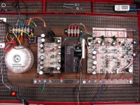
My problem is with a constant 120Hz hum that does not vary gain. I am currently using one common ground for power and signal (see attached image) and from my research, I think this is where my problem exists.
Over all the sound quality is good, with each section being actively filtered and driving components from my old car stereo which have been mounted in custom enclosures to fit my work bench.
Unfortunately I have yet to produce one large schematic showing the entire layout, but any help you can give me based upon my description and the attached images would be greatly appreciated.
In an attempt to build a large project that they can take with them at the end of the year, I have been working on a large breadboard amp that highlights all the different designs they see including everything from basic BJT CE amps all the way to LM3886 amps.
My problem is with a constant 120Hz hum that does not vary gain. I am currently using one common ground for power and signal (see attached image) and from my research, I think this is where my problem exists.
Over all the sound quality is good, with each section being actively filtered and driving components from my old car stereo which have been mounted in custom enclosures to fit my work bench.
Unfortunately I have yet to produce one large schematic showing the entire layout, but any help you can give me based upon my description and the attached images would be greatly appreciated.
Attachments
Hi,
The signal and supplies should use separate ground returns
to the star point. TBH you might have an intractable problem
using breadboards for the power supply, not really suitable
for that or typical speaker output currents for that matter.
rgds, sreten.
The signal and supplies should use separate ground returns
to the star point. TBH you might have an intractable problem
using breadboards for the power supply, not really suitable
for that or typical speaker output currents for that matter.
rgds, sreten.
Last edited:
If you use a ground bus then the connections must occur in the correct order, especially in the PSU. It is best to keep charging pulses off the ground bus, but the order of connection must be: rectifier out -- first (reservoir) cap ground -- second (smoothing) cap (if present) ground -- regulator ground -- rest of circuit.
People always seem to get the first few wrong and so inject charging pulses into either the PSU ground or the the circuit ground.
The thing you must impress upon your students is that the ground bus is not an equipotential plane, no matter how thick it is. It is a resistor/inductor and must be treated as such.
First and foremost, thanks to both of you for your replies.
sreten - Please excuse my system level ignorance, but what do you mean by "star point" in your reply? The common ground? Also when you refer to signal ground, are you talking about all ground returns within the amplifier section or just the return line to the input device?
DF96 - Thanks for the suggestion. I will try that out today and let you know.
The star point is the point used for ground in a star ground system. Note that for an audio system to work properly signal potentials usually have to be referenced to a ground potential and the only way to guarantee that is to use a single point as the reference. In reality all we can do is provide a physical approximation to a point. Departures from an ideal point can inject hum, although a ground bus (as you have) can work provided the connections are made in the right order.
Issues of grounding are not always properly dealt with in elementary electronics textbooks, which may be why so many people get them wrong. A common mistake is to have a star point but then directly inject charging pulses into it! Only a perfect (ideal) star can cope with this.
As I said, the best option is to treat every ground connection as a resistor/inductor. This forces you to think about where the currents go and what voltages they develop.
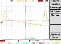
I made some of the changes you recommended and it has helped the noise level a good bit. The odd part is that the noise is now only present on the mid-range drivers. The only difference is that I am using the unregulated positive rail to drive this section. The power on just that section has fairly high ripple of about 150mVpp (see attached image) but ripple on the other power supply outputs is very clean. So I thought to check the ripple on the unregulated negative rail and the high ripple voltage is not present - I am however not using this rail for anything but as an input to my two negative regulators. For clarification, my PSU currently has six outputs: +/-44V (unregulated), +/-24V(regulated) for the LM3886 sub amp, and +/-12V(regulated) used for the active filters and the LM386 tweeter amp.
Thanks again for all your help.
Thanks again for all your help.
Attachments
Last edited:
- Status
- Not open for further replies.