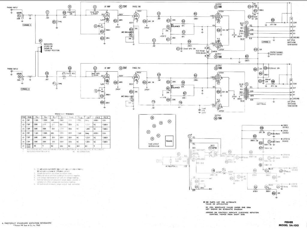
Maybe someone has experience with this amp or can read this schematic better than I. My question is concerning the anode to grid caps on the first gain stage. The amp I have does not have them installed and from what I can read the schematic calls for 2pF?
I'll take a guess in that the purpose of them was some frequency dependent feedback? 2pF and the 1Meg grid leak form a high pass filter w/ a -3db of 80kHz. Is this for stability? It seems fine at quiescent state but I haven't shot any square waves through it.
I would think since it's a high gain stage the series resistance with the grid would limit hf gain so maybe the anode to grid cap might be redundant?
They must have been removed for a reason and I am just curious if I should put them back in. I would like to make sure I put the correct value in too.
Thanks
-bird
2pF and the 1Meg grid leak form a high pass filter w/ a -3db of 80kHz.I would think
since it's a high gain stage the series resistance with the grid would limit hf gain so
maybe the anode to grid cap might be redundant?
The stage's gain amplifies the 2pF cap's effective value accordingly, like the Miller effect.
The 15pF peaking cap across the input 47k grid resistor helps to extend the hf response.
Last edited:
Hi Rayma,
I see the 15pF cap across the 4.7k grid resistor now. I am confused though, this small value cap is a really high resistance up until higher than what we can hear, at 100kHz it's still 100k. This is increasing high frequency response by making the input resistance lower (it and miller capacitance reduce the highs). I don't understand why then they go and add 2pF more anode to grid capacitance which like the miller capacitance is multiplied by the gain? So if the gain is 50x and there is already 2pF intrinsic anode to grid capacitance, then add two more makes 4 you can have quite a bit of input capacitance. It just doesn't make sense to me. Like hey let's boost the high's but then reduce them?
So I guess my other question is since there is essentially less miller capacitance with no 2pF cap, the input 15pF cap might be allowing too much high frequency noise though? Should I remove that 15pF cap too or just keep it and the 2pF cap? Seems like a strange thing to me is all and I don't think a company would waste caps in their design for no good reason so they must have a purpose other than to contradict each other.
Last edited:
I don't understand why then they go and add 2pF more anode to grid
capacitance which like the miller capacitance is multiplied by the gain?
I'd guess that the 2pF caps are there to help establish the input capacitance at a known value,
so that the peaking caps can then work more consistently. It's similar to how the compensated
attenuator in a x10 scope probe works. This also reduces and linearizes the hf phase shift.
http://www.ece.rochester.edu/courses/ECE113/labs/Lab_04.pdf
Last edited:
Okay so at higher frequencies the inductance of the resistor comes into play and so the 15pF cap is added. And the anode to grid capacitance of a 12AX7 may differ a little from one to the other so the 2pF cap is added to make Miller C more consistent and so the the input stage always behaves consistently regardless of valve used.
I think that makes sense if I have it correctly. Thanks!
I think that makes sense if I have it correctly. Thanks!
Okay so at higher frequencies the inductance of the resistor comes into play
and so the 15pF cap is added.
The main effect is the shunt 15pF across the 47k. This balances out the tube's input capacitance
to flatten the response, to first order anyway.
The main effect is the shunt 15pF across the 47k. This balances out the tube's input capacitance
to flatten the response, to first order anyway.
Right okay I think I got it now thank you.
Right okay I think I got it now thank you.
Look at the Citation I preamp's line section, there's a similar peaking circuit right after the volume control,
and also at the output cathode follower's grid. http://www.quadesl.com/schematics/hkcit1_sch.gif
Looking through more contemporary designs I am not finding any examples.
Seems like an old school thing. I guess I never paid much attention to these caps before.
Yes, this was a very popular technique in early tube audio circuits.
Both gain and bandwidth were sought after. Here's a Scott amp, same technique.
https://www.hifiengine.com/manual_library/hh-scott/299.shtml
Of course, folks like Tektronix had to take the tube circuit bandwidth/gain problem to a whole other level.
Here's a great Tek work on scope vertical amplifiers, with lots of their solid engineering detailed.
They literally wrote the book on the subject. http://www.davmar.org/TE/TekConcepts/TekVertAmpCircuits.pdf
Last edited:
I had a 299 that I sold and wish I hadn't. I have a nice Tektronix scope I still use almost everyday.
I downloaded that PDF you linked, it is a great addition for my library thank you.
Those guys were smart cookies!
For sure. Sadly, they're all gone now. A new owner may revitalize Tek, we'll see.
Fortive spinoff complete, Tektronix has new owner | OregonLive.com
I did not see this in the news! I was laid off in 2013 after 37 years.
Sorry about that, the suits ruin everything.
Can these old noval sockets get conductive or have issues? One channel has static noise that gets worse the longer it is on, if you wiggle the 12DW7 it makes terrible noises.
Swapping tubes doesn't help.
At first I thought it was a bad ground connection where the components are tied to the tag board, the tag board ground is riveted and when you wiggle the tag board it makes the same noise but it didn't fix it.
I removed all components soldered to the socket and cleaned them and then resoldered everything and that didn't help. I did the same with the tag board.
I replaced every component connected to that socket with no help.
Someone else before me couldn't figure it out but I noticed they replaced a pin in that 12DW7 socket.
The only thing I can think of is the socket itself but I have never had this problem before. I am just trying to get some advice before I go in and remove everything again and replace the socket.
Hi yes I am well aware of interelectrode capacitance. Is this in regard to the noise issue or were you just commenting on the original discussion about the 2pF cap added from anode to grid? My thoughts on the latter was that the intrinsic capacitance was not a good thing which is why I was puzzled they would add more but Rayma has clearly explained the reasoning behind it.
The only thing I can think of is the socket itself but I have never had this problem before. I am just trying
to get some advice before I go in and remove everything again and replace the socket.
If only that channel does it, then it's either the socket, or a component or wire soldered to one of the pins.
Poke at things with an insulated stick and see if you can get the noise. If not, odds are it's bad pins in the socket.
The only thing I can think of is the socket itself but I have never had this problem before. I am just trying to get some advice before I go in and remove everything again and replace the socket.
It's an extremely rare occurrence, but yes, I have encountered bad sockets. I suspect contamination in the molding compound.
- Status
- This old topic is closed. If you want to reopen this topic, contact a moderator using the "Report Post" button.
- Home
- Amplifiers
- Tubes / Valves
- Fisher SA-100