Yes, my error in inserting the leading "1"s.
I don't understand how Q01/Q03 limit current. They would provide added current to the load, providing added power that doesn't have to be sourced directly by the IC.
Perhaps the OP could advise the Volts/Div in his scope photo? Thanks.
I don't understand how Q01/Q03 limit current. They would provide added current to the load, providing added power that doesn't have to be sourced directly by the IC.
Perhaps the OP could advise the Volts/Div in his scope photo? Thanks.
Here's the datasheet for the stk086 : https://pdf1.alldatasheet.com/datasheet-pdf/view/82561/ETC/STK086.htmlDid you located exactly that stk connection diagram ? If so ,then maybe both stk are faulty or fake ,and failure repairing was reason to recycle it .
You can also perform some checks .
1. How waveform changes ,if you adjust volume ?
2. Measure idle current of each stk , by disconnecting trace from pin8 or pin6 and passing it thru dc dmm in 10amp mode . If we see crossover distortions, then ammeter should show zero or almost zero with no signal.
When you compare this to the actual amp it looks exactly the same except for the current limiting circuit and the input muting circuit.
Only thing different on my actual example of the amp is that both pin 5 and 9 (respectively -1.3V and +1.2V on the schematic) actually measure -0.04V and + 0.05V on both channels give or take a few mV.
1. The distortion is still present but as the sine wave gets bigger it ends up looking like a tiny little notch (with the distortion analyser the thd gets lower when volume goes up. Also the lower the frequency the less distortion is present.
2. I'll measure this tomorrow and let you know.
These are really small signal transistors, I doubt these are there to add current. Also their collectors are connected to the bases of the drivers (in the stk) which are only supposed to be at 1.2V.Yes, my error in inserting the leading "1"s.
I don't understand how Q01/Q03 limit current. They would provide added current to the load, providing added power that doesn't have to be sourced directly by the IC.
Perhaps the OP could advise the Volts/Div in his scope photo? Thanks.
The picture is with low volume, about 0.8V RMS into 8ohm load
Inside stk in positive rail is current source ,in bottom side voltage amplifier. They both are not powerful to drive speaker directly. So if you overload output in example , on 0,47ohm resistor will be voltage drop ,lets say 1v , and one of those small q01 or q03 transistors ,depending on current direction ,begin to conduct ,and short input for power transistors ,tr7 or tr8 inside stk . Output current drops to some value ,thats like some additional feedback.
Measure resistance pin 5 to 9 , if idle transistor inside stk shorted ,you will not have idle current and you can't fix that externally.
Measure resistance pin 5 to 9 , if idle transistor inside stk shorted ,you will not have idle current and you can't fix that externally.
My bad. I assumed Q01/Q03 were outboard power transistors; I also construed a high current path from their collectors to B+/B-.
I retract my previous diatribe. 😕
I retract my previous diatribe. 😕
he verdict is : both stk's are bad. I tested on both drivers from base to collector (pin 9 to 8 and pin 5 to 6) and on one side I get a little more than a diode drop because of R11 but on the other side I get nothing (both ways). I repeated this test on the second stk with the same results. So both stk's have one driver with an open base to collector junction 🙁. I think I will try to put two different amp module in there, maybe the MX50SE I have already built and never used which correspond to the power supply of the fisher, add a little protection circuit and use it as a bench amp. It was probably never a great performer but it looks good enough to not throw away. Thanks for the help !!
If you wanna put different module ,you need ensure similar voltage gain ,its determined by feedback resistors ratio . Too low gain will result in less output than possible , too high gain in noise and too early overload and distortions . Some old amplifiers had higher sensitivity line inputs ,not 2v as now .
Actually the MX50SE are complete boards, I'll just remove the whole board that is in place now with the stk's and just rewire the inputs to the new boards, connect power supply (maybe with some fuses) and add a relay board. They physically fit on the existing heatsink, I'll just have to drill some new holes.
Yes ,that is good solution . According to stk datasheet ,it had 0,2% distortion ,and its output was assymetric . Old technology would not sound best as possible ,so another module or board ,with better parameters is like upgrade .MX50SE has kinda similar schematic as stk inside ,but complementary output .
Most of these stk's, apart from reliability problems, don't actually have terrible specs but I sure am all for discrete components !!
Some stk were released in different versions ,generations ... I , II ,V ,XI ... I was interested some years ago in building amplifier with one of those ,with xii at end ,but read about oscillation problems and changed my mind. In XII version ,if i remember correctly, pinout same ,but distortions lower than II version .
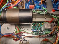
I just finished installing the MX50SE modules and it turned out pretty good. Nothing really exceptional but I'm getting clean power (0.02 ~ 0.04% distortion) all the way up to 57W from 15 to 26Khz. There possibly is room for improvement because I used the cheap components that were delivered with the kit, also bias is higher on one channel and not adjustable but I'm quite happy with the way it turned out. Also I happened to already have a little 12V transformer that is perfect for the protection board and fit nicely in there as there's a lot of room in these. Plenty of space on the right to fit the relay board.

My main amp is a Sansui BA-3000 with its complementary pre so I don't think this one will come even close. I think I'll either use it as a bench amp or just keep it as a project to experiment.
I have a Sansui BA-1000, never tried it with speakers, kept in reserve, at 120W / channel it is too much for my current house.
Legendary sets.
Legendary sets.
I love Sansui and have had a lot of their gear but never had a chance to test that one. There's no need to use the full 120W though !!
The original speakers are at another place, the biggest ones I have are rated 60W.
And my current sound level is about 2W/channel most of the time.
And my current sound level is about 2W/channel most of the time.
Hi all,
I have in my hands an Emerson Selene amplifier (6250).
It originally mounted SS1001 but they were faulty.
I replaced them with a couple of new STK086 (they are not SANYO, but I bought them from a well rated supplier on Amazon) and I have exactly the same issue reported in this thread.
Both channels work but I have distortion (identical on both channels).
The schematic is very similar to the one posted above (Fischer CP7000).
I have alredy replaced all electrolitic capacitors, no other components appear faulty.
I am struggling to fix this issue, I was wondering about the fuctionality of C07 (12pf) connecting pin 3 and 5.
Could this value impact on crossover distortion ?
Thank you,
Alberto
Last edited:
- Home
- Amplifiers
- Solid State
- Fisher CP-7000 distortion