Interesting. I wonder why he did it. Does anyone know when this revision change took place and whether other revisions were made?A resistor.
Take a look at rev.1 of the J2 at Issue 34 – Magazine | TONEAudio MAGAZINE page 175 (in the High Resolution Version). More simple than rev.0
Looks like Nelson also removed the active bias system for the output JFET in rev.1!? 😕
I recently ordered a brand new First Watt J2 from the Hungarian distributor which should be here within the next two weeks. I'd really like to know whether I would be getting the most recent revision if nothing else for the fact that I like having the latest 'n' greatest from the man himself. 😉
Thank you. Clipping won't be an issue for me. I'll use my pair of Audio Note AN-E speakers with it at first (93 dB/W/m). Later once I have enough money saved up I'll probably spring for a pair of Teresonic Ingenium XR speakers (using Lowther DX4 drivers, 103 dB/W/m). They sound like heaven.there is no audible difference between R0 and R1 , except in heavy clipping state ;
You wouldn't happen to know when the revision change took place?
let's say that - theorethicaly - R1 will stretch slightly more ;
but - speaking in db range - do not even think about .
in case that Papa made some radical change - from functional view , I think all R0 will be called back to kitchen table
so - that was not a case ....... conclusion is simple - relax and enjoy

but - speaking in db range - do not even think about .
in case that Papa made some radical change - from functional view , I think all R0 will be called back to kitchen table
so - that was not a case ....... conclusion is simple - relax and enjoy

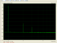
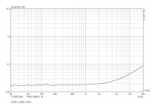
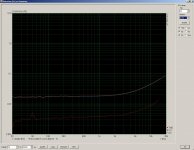
Here is something akin to a J2 clone ... still work in progress but it plays rather good already. 🙂
Do you know which sch be built for this amplifier?Would you please post the sch.thanks
Do you know which sch be built for this amplifier?Would you please post the sch.thanks
If you are asking for the J2 schematic, please refer to post 20 in this thread. I think we need to respect Nelson's wishes.
If you are asking for the J2 schematic, please refer to post 20 in this thread. I think we need to respect Nelson's wishes.
Thanks for you remind.
I try again...
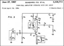
Hi Tazz, let me guess your output stage:
It's like rev 1, and rev 1 is the attached pic, but with:
1. Zener replaced with resistor Rxxx (rev 0 used TL 431)
2. R2=R6, C4, VR left out, R1 chosen to provide symmetric drive for a given load, Rxxx and R5 (Nelsons grab box... ;-)))
Can you post your solution with your schematic - measurement looks beautiful. Can you post measurement with different loadspeaker loads??? (In my opinion a weak point)
Regs, Dirk
Attachments
Hi Tazz, let me guess your output stage:
It's like rev 1, and rev 1 is the attached pic, but with:
1. Zener replaced with resistor Rxxx (rev 0 used TL 431)
2. R2=R6, C4, VR left out, R1 chosen to provide symmetric drive for a given load, Rxxx and R5 (Nelsons grab box... ;-)))
Can you post your solution with your schematic - measurement looks beautiful. Can you post measurement with different loadspeaker loads??? (In my opinion a weak point)
Regs, Dirk
I've asked NP directly, and he's OK with having DIY designs for a J2 clone posted in the forum. He does not want a J2 official schematic out, but short of that, he's indifferent to DIYers posting their creations.
In light of the above, I suspect we will be seeing a few schematics in the next few weeks.
I'll leave it to the folks who made the designs to post them, but I've been privy to a few J2 clones.
Hopefully, the designers will feel comfortable moving this DIY amp forward via the forum.
I just looked at the thread and there was some new discussion. I'm always looking forward on papas opinion on the possible solutions presented. I always like to understand more...
I did not use a voltage reference but an optocoupler to set the bias the led senses the current passing through the upper fet source resistors and the phototransistor actuates the vgs seen by the upper fet in order to set and maintain the bias. A comparatively large capacitor in parallel takes care of the AC content and limits any adjustment of the bias to very low frequency.
If it is okay with NP I can post my schematic wich I believe is fairly close to the real j2 in a weeks time or so.
If it is okay with NP I can post my schematic wich I believe is fairly close to the real j2 in a weeks time or so.
I've asked NP directly, and he's OK with having DIY designs for a J2 clone posted in the forum. He does not want a J2 official schematic out, but short of that, he's indifferent to DIYers posting their creations.
Just for clarity, I find the lack of an official schematic discourages commercial
cloners, so there is no such thing.
Better that you guys exercise your DIY muscles anyway.
😎
- Home
- Amplifiers
- Pass Labs
- FirstWatt J2