First Watt CSX2 simulation and build
I have completed F2J, it was fun, great funny amp that heats lower when you play louder, thanks to Mr. Kirchhoff.
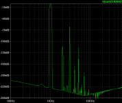
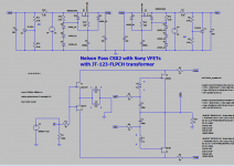
While waiting for TFH-51S VFETs from Japan and plans from Mr. Pass it's time to build something different. As I have a few pairs of 2sk82/2sj28 and I like a minimalist approach I created a simulation of CSX2. I used fully symmetrical spice models from Mike at Audiomaker - the capacitancies are not specified. The THD at 1W 8 Ohm is 0.098159% (3rd harmonics at -60dB FS). The gain is only about 2.81x. I biased them at 1.5A as per Papa's recipe.
I have used JT-123-FLPCH instead of JT-112-L as I have a pair purchased a few years ago for F6 - not sure if there is any disadvantage of using them in CSX2.
Has anyone built this amp? I would like to design PCBs. I am wondering if you could share some hints, ideas, for example what size of heatsinks have you used, any photos? Would be grateful for sharing your experience 🙂

I have completed F2J, it was fun, great funny amp that heats lower when you play louder, thanks to Mr. Kirchhoff.
While waiting for TFH-51S VFETs from Japan and plans from Mr. Pass it's time to build something different. As I have a few pairs of 2sk82/2sj28 and I like a minimalist approach I created a simulation of CSX2. I used fully symmetrical spice models from Mike at Audiomaker - the capacitancies are not specified. The THD at 1W 8 Ohm is 0.098159% (3rd harmonics at -60dB FS). The gain is only about 2.81x. I biased them at 1.5A as per Papa's recipe.
I have used JT-123-FLPCH instead of JT-112-L as I have a pair purchased a few years ago for F6 - not sure if there is any disadvantage of using them in CSX2.
Has anyone built this amp? I would like to design PCBs. I am wondering if you could share some hints, ideas, for example what size of heatsinks have you used, any photos? Would be grateful for sharing your experience 🙂
Attachments

Last edited:
Well, you are in luck. JT-112-LCF and JT-123- FLPCH are electrically identical. 🙂
Thanks for that Dennis, I've seen some small differences in the spec, but probably they are not so important. 🙂

I asked Jensen about that a few years ago and was told they were in fact electrically
identical, despite the diff in the spec sheets.
The late member permaneder designed a board for CSX1 but I don't remember if
anyone made one for the CSX2.
Anyway, have fun with your pcb design.
Cheers,
Dennis
identical, despite the diff in the spec sheets.
The late member permaneder designed a board for CSX1 but I don't remember if
anyone made one for the CSX2.
Anyway, have fun with your pcb design.
Cheers,
Dennis
I asked Jensen about that a few years ago and was told they were in fact electrically identical, despite the diff in the spec sheets.
This is great news, Dennis.
Papa said it dissipates 100W per channel, so if I use two 0.5 K/W on the side I should be fine.
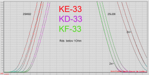
In the meanwhile, I need to curve trace the VFETs and find out how to mount them on the flat heatsinks.

5mm thick aluminum T profile should do the job... I hope.
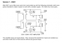
The T bracket will work fine and was used in the Sony Vfet 2 project kit:
Sony Vfet Illustrated build guide
Sony Vfet Illustrated build guide
The T bracket will work fine and was used in the Sony Vfet 2 project kit
Wow, that's a really nice build, I would mount the T profile a bit lower... probably.
Attachments
Last edited:
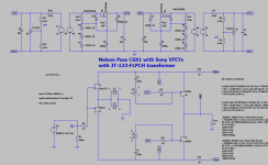
taking in account less critical drive/ better transfer of xformer, I would go with CSX1
I thought it might be a good idea to avoid dealing with these capacitances. I need to order a new transformer(s) anyway so there is no difference if I ask for extra 12V windings 🙂
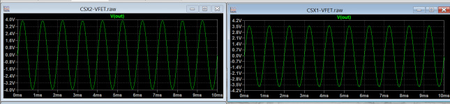
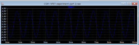
Not sure why, the gain in CSX1(at least in my simulation) is 2.51x, comparing to 2.81x in CSX2, both idle currents are 1.5A. Both output voltages attached, the input voltage amplitudes are the same 1.424V
Also Mr. Pass used an extra transformer, not an extra 12VAC windings.
Also Mr. Pass used an extra transformer, not an extra 12VAC windings.
Attachments
Last edited:
aha, these two 1K
dunno, my brain is now pretty much bzzz (being long day) so I'll left it for 'morrow
edit: that mus be checked in vivo, amount of change
there will be some, but how much , depends of stiffness of bias voltage generator ..... and now I don't have eyes open enough to see is there some difference between Papa's prescribed biasing circuit and your sim
Last edited:
there will be some, but how much , depends of stiffness of bias voltage generator ..... and now I don't have eyes open enough to see is there some difference between Papa's prescribed biasing circuit and your sim
no problem, same here. Thank you for helping me with this.
After a few years after buying Sony vfets, I measured them... today, all 14 (6N + 8P) pieces are good 🙄
Attachments

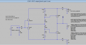
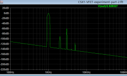
I was wondering why do we need a transformer in CSX? In both gates we get the signal in the same phase, so I did an experiment and... removed it ... The only drawback I see so far is that the output signal is inverted but that's not a big issue.
Total Harmonic Distortion at 1W 8Ohm 1kHz: 0.098483%, 2nd: -90dBFS, 3rd: -60dBFS
Gain at 1kHz: 2.76x, 8.8dB
What I am missing here? 🙂
Total Harmonic Distortion at 1W 8Ohm 1kHz: 0.098483%, 2nd: -90dBFS, 3rd: -60dBFS
Gain at 1kHz: 2.76x, 8.8dB
What I am missing here? 🙂
Attachments
Last edited:
think about rails ripple
Despite that there is a capacitance multiplier? I think the original CSX1 and 2 are both prone to the rails ripple?
Last edited:
- Home
- Amplifiers
- Pass Labs
- First Watt CSX2 simulation