Are there any PP amps that use a PCB instead of point to point?.....Tubelab has a simple PP circuit board.
I also have parts kits for the Simple P-P that contain all of the components that go on the PC board so you don't have to chase down the parts your self.
Before you spend any money on an amp get a pair of resistors that are about 2 or 3 ohms and at least 5 or 10 watts. Connect them in series with your speakers and the amp that you use now. This will simulate the relatively high output impedance of a SE tube amp that doesn't use feedback. Listen to some music that you are familiar with paying attention to the bass. Some speakers will lose bass response, while others will appear to have more bass, but the bass will be loose and uncontrolled. I a really bad case it will sound like the kids boom - boom car down the street, all one note. Also listen to the vocals, especially a female to see it the crossover frequencies get screwed up.
Your speakers were designed in the 60's when most amps still glowed and even the solid state amps had somewhat poor damping factor. Although SE amps were rare the speakers could do OK.
The SPP, SY's RLD, and the ST-35 are representative of mid powered tube amps sold at the time the Sony speakers were made.
Sorry if I haven't gotten back to everyone in a timely fashion. There is a lot of stuff to read up on here! I think I have decided to go ahead with the tubelab simple p-p. As much as I like the idea of going to SE i think a P-P would be better. It also looks like it is going to be relatively cheap to build. I am leaning towards going with Edcor power and OT but the budget would accept James. Any good resources for James transformers? George thanks for the tip on the resistors, sound no likey 😛. As soon as a pair of speakers that I am selling gets picked up I will be sending you off an order for a board and kit. Thanks to everyone's help!
I will keep you updated once I start the build.
I will keep you updated once I start the build.
You can etch u'r own and go 30 watts/ channel triode mode PP for under $450. Healthy enough to drive inefficient 89db 4ohm speakers.....
Toner transfer for etch resist..
Thee is also the ST35 PCB at 18watts/channel and Millets big red PCB for 20 to 125 watts/channel.
Toner transfer for etch resist..
Thee is also the ST35 PCB at 18watts/channel and Millets big red PCB for 20 to 125 watts/channel.
Attachments


I can second or is it third for the tube lab amp. I built the the tubelab SE and there was enough support for even a simpleton like me to be able to get a great result.
I am leaning towards going with Edcor power and OT but the budget would accept James. Any good resources for James transformers?
The Edcor stuff is a great value, and don't hesitate there, since there is typically a 5-6 week lead time to get your iron. Edcor now also sells chokes, so power, choke and output all from Edcor may be the way to go.
James is a bit tough to get in North America, and shipping from Asia is $$. The one distributor that I can think of is TCtubes.com but they are holding off on ordering James transformers due to exchange rate issues according to their web site.
You can contact James Transformers directly, and order from them, the prices are great, but the shipping.........
Also try Ebay for James, they are hit-or-miss on there.
As for tubes, JJ EL84's are inexpensive and perform well.
Toner transfer for etch resist..
Please share additional details, tips, tricks, etc. I have played with this slightly and it was a miserable failure.......assuming that you use a household iron for the transfer to the PCB.
Are you using special paper and do you run it through the printer multiple times?
Hi Casper222, with the speakers capable of 98db/1w/1m & 16 ohm impedance, I can't think of anything better than OTL amp - they work best with high impedance load.
I would suggest as a option, to check some of kit amplifiers from transcendentsound...
Max
I would suggest as a option, to check some of kit amplifiers from transcendentsound...
Max
The best results of the toner transfer method are dependent on the "toner" and the paper used. I used copies made at the local Office Max and they looked great but did not work.
RICOH with the contrast set on the dark side, or running the sheet through twice to double up on the toner have produced the best, thickest toner layer to transfer. The "Paper" is HP slick presentation paper which was chosen for its high clay content. This paper falls apart when soaked in cold water and releases from the PCB.
The copper must be clean and I use steel wool to give it a little surface finish to grab the toner. The iron is cranked up as hot as it gets and I start in the middle and work my way to the edges being careful not to let the paper slip in respect to the PCB. Turn the iron in its edge to apply heat with higher pressure and work it over the entire PCB. let cool and soak in cold water for 15-20 minutes. The paper will peal off of the PCB but leave a layer of clay on the outside of the toner and this is OK. Dry and verify that the pattern is intact. If a trace did not transfer or pull off, I use vinyl head cement from fly tying to correct the pattern and a knife to trim the excess.
Etch is the stuff from Rat Shack, I use zip lock bags as etch tanks to contain the mess. Warm the enchant prior to use to get a 15 minute etch.
Clean the toner off with MEK etc.. and then steel wool the copper and use tin plate to protect the copper. (from Mouser) The back side is done.
For the front is done like the back but with additional steps.
The front is sanded with 320 prior to steel wooling it to get a grip surface for the front side graphics, and after the paper is removed I use lava soap to slowly remove the layer of white clay from the layer of toner. If you are too energetic, you will also remove the toner so go slow.
Dry the PCB and spray the top with a coat of clear enamel to protect the graphics.
Drill with proper hole size, as small as possible and for feed throughs I use brass eyelets from Antique Electric Supply in Phoenix. You will need a 45deg awl to spread the barrel prior to flattening it. Always solder the eyelet well to the PCB for a good connection.
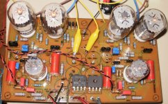
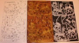
PCB is completed.... The post above was done this way. It shows the artwork layers and the PCB as completed prior to the eyelet installation.
RICOH with the contrast set on the dark side, or running the sheet through twice to double up on the toner have produced the best, thickest toner layer to transfer. The "Paper" is HP slick presentation paper which was chosen for its high clay content. This paper falls apart when soaked in cold water and releases from the PCB.
The copper must be clean and I use steel wool to give it a little surface finish to grab the toner. The iron is cranked up as hot as it gets and I start in the middle and work my way to the edges being careful not to let the paper slip in respect to the PCB. Turn the iron in its edge to apply heat with higher pressure and work it over the entire PCB. let cool and soak in cold water for 15-20 minutes. The paper will peal off of the PCB but leave a layer of clay on the outside of the toner and this is OK. Dry and verify that the pattern is intact. If a trace did not transfer or pull off, I use vinyl head cement from fly tying to correct the pattern and a knife to trim the excess.
Etch is the stuff from Rat Shack, I use zip lock bags as etch tanks to contain the mess. Warm the enchant prior to use to get a 15 minute etch.
Clean the toner off with MEK etc.. and then steel wool the copper and use tin plate to protect the copper. (from Mouser) The back side is done.
For the front is done like the back but with additional steps.
The front is sanded with 320 prior to steel wooling it to get a grip surface for the front side graphics, and after the paper is removed I use lava soap to slowly remove the layer of white clay from the layer of toner. If you are too energetic, you will also remove the toner so go slow.
Dry the PCB and spray the top with a coat of clear enamel to protect the graphics.
Drill with proper hole size, as small as possible and for feed throughs I use brass eyelets from Antique Electric Supply in Phoenix. You will need a 45deg awl to spread the barrel prior to flattening it. Always solder the eyelet well to the PCB for a good connection.
PCB is completed.... The post above was done this way. It shows the artwork layers and the PCB as completed prior to the eyelet installation.
Last edited:
Thanks, excellent description! Your PCBs look great. I'll have to try this again. I was also attempting to use this technique for front panel graphics (without success).
- Status
- Not open for further replies.
- Home
- Amplifiers
- Tubes / Valves
- First Tube Build, Thoughts?