I uses one of the pages in the where to start sticky and got this. If some one would over look it and make sure i did not create a time bomb instead of an amp it would be appreciated. also any input on a way to improve it would be nice, this is my first try so the more i can learn the better.
one last thing is there a page that tells what amplification factor to look for in a pre amp and power amp, and how this applies to output "iv seen an amp factor of 5 with a typical out put of 15w and then another with a factor of 10 with the same end power"
Iv only looked at page one of the where to start thread, so if its some where in there just ignore it.
Attachments
Is there a particular design that you would like someone to look over? 😕
The gain you will need from a preamp will depend on the input sensitivity of your power amp (the input voltage required for full output). The input sensitivity itself depends on the gain of the amplifier.
The gain you will need from a preamp will depend on the input sensitivity of your power amp (the input voltage required for full output). The input sensitivity itself depends on the gain of the amplifier.
the pre amp stage hit me after posting. if I'm right, "i may not" at full gain the pre amp would need 10V more to use the full ability of the power amp section.
it should show this time

it should show this time
Oh, sorry. For some reason I couldn't see the attachment before.
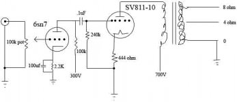
Well, that circuit appears to be sound (pardon the pun) at first glance. The output stage may benefit from a cathode bypass capacitor of some sort, either from cathode to ground (conventionally), or from cathode to B+.
What do you intend to use as the primary impedance of the OPT?
Marking of anode and cathode voltages would be useful.
As for possible ways to improve the circuit, a more capable driver than a 6SN7 may be required - also, it may not have the required gain (it will be 18.5 or so) to drive the output valve to full power. What is the idle voltage of the grid wrt the cathode at idle?
 The B+ of 700V is quite dangerous, and you should be thinking seriously about building an amplifier with a lower HV requirement, especially as a first project. In any case, lower voltage power supplies are generally cheaper to build.
Well, that circuit appears to be sound (pardon the pun) at first glance. The output stage may benefit from a cathode bypass capacitor of some sort, either from cathode to ground (conventionally), or from cathode to B+.
What do you intend to use as the primary impedance of the OPT?
Marking of anode and cathode voltages would be useful.
As for possible ways to improve the circuit, a more capable driver than a 6SN7 may be required - also, it may not have the required gain (it will be 18.5 or so) to drive the output valve to full power. What is the idle voltage of the grid wrt the cathode at idle?
The B+ of 700V is quite dangerous, and you should be thinking seriously about building an amplifier with a lower HV requirement, especially as a first project. In any case, lower voltage power supplies are generally cheaper to build.+700 is a little much for beginning, mmm? I haven't even tried 811 yet...
May I suggest oh Idunno uh 12AX7 for starters? lol 🙂
Tim
May I suggest oh Idunno uh 12AX7 for starters? lol 🙂
Tim
You might want to take a look at a 6BL7 to drive the output stage. A three stage amp might work better with that output tube though. How about a ECC99 into a 12B4A into the output tube. You could probably direct couple the first two stages. I have to go to work so I don't have time to explore this combo but I suspect it may work well. You really need to put some gain and some current into the 811 to get into it's "sweet spot" from what I understand.
thanks for you posts I more or less wanted to see if i did the math right and such, I'm more into PP but thought SE would be an easy place to start.
Let me see if I've got this right. The grid would be run at -40v so for full output with out clipping i want an input of 38v or so, so the Gv never drops below 0v. so with a 2v input with that pre "paper says gain of 15" would that be 17v out, 30v out, or is there some formula for this?
As with high voltage, I know how to be safe. some of the stuff iv done as side jobs in the past has gone past 2.2Kv.
If Vgk is -40V at idle, you'll be looking for 40Vpk (28.3Vrms) for full output. To be able to get full output from a standard CD player output (2Vrms), you'll be needing a gain greater than 14.1, which is achieved by this driver stage.
@audiousername
You said the full output for a cd player was 2vrms
Am i mistaken or is that american line voltage....
Because i learned that a cd player gives 0db line-level
here in europe line-out 0db = 0,707v rms...
????
(sorry for being a little off-topic)
You said the full output for a cd player was 2vrms
Am i mistaken or is that american line voltage....
Because i learned that a cd player gives 0db line-level
here in europe line-out 0db = 0,707v rms...
????
(sorry for being a little off-topic)
0dB with reference to what?
Have a look at the manual of your CD player, it should list its analogue output level in the specifications table, which more than likely will be 2Vrms
Have a look at the manual of your CD player, it should list its analogue output level in the specifications table, which more than likely will be 2Vrms
- Status
- Not open for further replies.
- Home
- Amplifiers
- Tubes / Valves
- First try, Would some one look over.