Looking better and better, Itsik. I have minor suggestions:
1. Allow more space and multiple holes for the coupling caps, so that you could experiment with big, fat ones.
2. Move pad1 & 2 to the left of socket to clear the center. I like to drill the center to mark holes on the chassis, as well as providing better ventilation under the sockets.
3. Provide independent pads for pin 4 and 5 of the front (center) tube. That way you could experiment - easily try a 6DT8 tube, in stead of your 12AT7, for example. (Knauf1919 did that in his layout).
Good luck.
Last edited:
Hi
Not sure if you guys read a lot about the RH84, the use of a cathode CCS is actually worst, you are better off using a simple power resistor + bypass cap. Also many valve gurus on this site recommend using a pentode instead of a triode at the Input stage, the Schade effect will be much better. This could be discussed in a different thread but since you are taking the time to create a nice PCB you might as well base it on the better improved RH84. (I’m not talking about RH84 ver2)
Nice work and progress on the PCBs.
BR
Eric
....Not sure why the Digikey Trace width Calculator link shows as 'blocked' in my last post-....
This forum's software tries to pick-up a "nice name" for an external link by requesting the "header" of the link.
Some other web-server softwares are reluctant to supply a header without a body. One seems to return the word "blocked". As you say, the link is perfectly valid (and does not seem to be about money). You "can" go back and Edit your message with a "nice name".
DigiKey doo hickey
Attachments

Hey all, I seemed to stop getting notifications and missed these updates. I will review them and incorporate the comments.
Thanks alot!
Thanks alot!
Hi
Also many valve gurus on this site recommend using a pentode instead of a triode at the Input stage, the Schade effect will be much better.
Nice work and progress on the PCBs.
BR
Eric
Eric,
I disagree- personal opinion really... I've built 3 different pentode preamp PP amps using same iron-
ChiFi 6F2, Audio note Rev E & Rev F (6U8A)... which sounded fine, but prefer latest 'board w/the Hi mu triode(ECC832)preamp design of the Dynaco ST-35. Lower zero sig noise, cleaner Hi's... but 50% or so lower gain. Which is fine for my app since I have NE5532 tone control pre/preamp in.
Jim
ps. what is the 'Schade effect'?
Last edited:
This forum's software tries to pick-up a "nice name" for an external link by requesting the "header" of the link.
Some other web-server softwares are reluctant to supply a header without a body. One seems to return the word "blocked". As you say, the link is perfectly valid (and does not seem to be about money). You "can" go back and Edit your message with a "nice name".
DigiKey doo hickey
Interesting
Schade feedback is a local feedback (not global) connected between the plate of the output tube and the driver plate via a Resistor. Lots of info about it on this site.
Last edited:
Hi
Not sure if you guys read a lot about the RH84, the use of a cathode CCS is actually worst, you are better off using a simple power resistor + bypass cap. Also many valve gurus on this site recommend using a pentode instead of a triode at the Input stage, the Schade effect will be much better. This could be discussed in a different thread but since you are taking the time to create a nice PCB you might as well base it on the better improved RH84. (I’m not talking about RH84 ver2)
Nice work and progress on the PCBs.
BR
Eric
I have done some reading on the RH84 on this site, regarding use of 6AU6 pentodes as drivers etc.
For now, I'm sticking to the original design as I've got alot of 12AT7's/6201 and want to use those.
Regarding the CCS, I didn't encounter any specific topics discussing this. If you have any links to the "Improved RH84", please share.
The change to zener and CCS were done together in rev2, so by removing the CCS the zener may need to be changed as well ?
The RH84 with the 12AT7 does sound good but from what I read many times this design can be improved further. The site Bartola has some good exemple of Schade feedback.
For the cathode CCS, it’s not specific to the RH84. I have never compared a cathode CCS to a regular resistor + bypass cap. I was recently reading about it. See here ; Cathode Bias CCS ... again
For the cathode CCS, it’s not specific to the RH84. I have never compared a cathode CCS to a regular resistor + bypass cap. I was recently reading about it. See here ; Cathode Bias CCS ... again
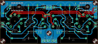
Here is my final (likely) layout...there are a few improvements from the previous one:
1) Split noisy power ground from quiet signal ground
2) Moved everything to bottom layer so that the heaters can now be routed across on the top layer
3) Bigger coupling cap (37.5mm)
4) Split/dual-mono (shared ground) B+ routing.
5) Symmetrical (mostly) parts layout between sides
6) Secure mounting of LM317 with heatsink
Most of the suggestions came from a professional designer which helped review the board and improve it iteratively.
Since I'll have a few PCB's with the min. order, I plan on making a few versions.
The first is going to be compact/economy build with Edcor OPT and CLC PSU with SS rectification. Curious to see if this will be sufficiently quiet for a Headphone amp... in my 45 a CLC was not sufficient.
For the second build, which will be a bit bigger and more expensive, I have a Maida regulator for B+ and plan on using 5U4G or 5AR4. I also have a pair of Lundahl LL1663 and O'netics 5K pri OPT to try.
Attachments
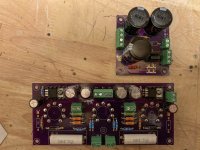
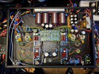
The boards arrived and from the initial testing they work great.
Voltages check out and with some big OPT's I have for a different project it sounds really really good.
For PSU, I've tried a CLCRC with one of the toroidal Antek chokes and there is no hum at all, totally silent background.
Voltages check out and with some big OPT's I have for a different project it sounds really really good.
For PSU, I've tried a CLCRC with one of the toroidal Antek chokes and there is no hum at all, totally silent background.
Attachments

Looks great!
Just spitballing here, so hope this is appropiate to this thread.
I've been doing a bit of thinking about tubes and PCBs recently. I very much enjoy giving old tube gear a new lease of life, and PCBs don't always make this job easier. For instance, substituting similar tubes with different heater requirements, or similar tubes with different pin-outs.
Likewise, shoehorning a PCB into a chassis design is not always easy, and tolerances must be exact. Output tubes could generally be offboard, but a PCB fixes a layout exactly.
Would it have been possible with your PCB provider to have had holes in the PCB where the tubes go, with pads around the holes? Something a bit like a Quad 2 input/driver board, where the board fits around the chassis mounted sockets?
Advantages would be:
- more tube choice
- heaters routed independently of PCB
- socket firmly anchored to the chassis, easing tube changing
- better socket choices. I cracked the base of 1 tube using a new Chinese porcelain socket, the pins were so tight.
- Freely available NOS B7G or B8A tubes instead of B9G popular items.
- simpler PCB due to use of connections onto the socket itself.
- simplify chassis layout.
Looks very much like the direction I am trying to go, but maybe having the sockets for ther input tubes located within the PCB, in a hole, to minimise lengths of wires.
Do you know of other solutions for screw connectors? I don't like the risk of making a mistake when reconnecting a board, and I have been looking to see if there are multi connector plugs and sockets that would simplify maintenance (a bit like the connectors on the back of a car radio).
Do you know of other solutions for screw connectors? I don't like the risk of making a mistake when reconnecting a board, and I have been looking to see if there are multi connector plugs and sockets that would simplify maintenance (a bit like the connectors on the back of a car radio).
They make 'em every day. Think Molex or Amphenol or any number of other Asian makers.
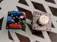
Or why not make a small PCB that mounts to the chassis socket, and use a ribbon cable to the board? You could even use that orange flex cable they use in hard disks if you wanted...
I designed this one to be pretty fool proof though. The terminals are numbered like the pins on the socket... Connect 7 to 7 etc... And all wires are different colours, too 🙂
If the circuit is simple enough, the PCB is small enough to hole the socket perfectly well enough, too.
Here's a pic of a 6J1P triode strapped simple gain stage I designed (to drive a 6E2 level meter on another board of similar size).
Attachments
Last edited:
Looks very much like the direction I am trying to go, but maybe having the sockets for ther input tubes located within the PCB, in a hole, to minimise lengths of wires.
Do you know of other solutions for screw connectors? I don't like the risk of making a mistake when reconnecting a board, and I have been looking to see if there are multi connector plugs and sockets that would simplify maintenance (a bit like the connectors on the back of a car radio).
Belden makes PC board sockets that also have the chassis mount saddles so you can do what you are thinking. then the Pc board is supported solely by the traditional tube saddles, no need to use the mounting holes on the PC board and fewer ugly screws showing on the chassis top. And as you say the tube sockets are rock solid on the chassis insertion wont flex the board at all.
Ya just realize the footprint is not the same as other sockets, and you don't need to spend Belden money to get sockets that style. GD-Parts sells a version (can't tell a difference from it and Belden) for 95 cents.
Wholesale Buy Various Tube Guitar Amp DIY Repair Parts from mafaudio Vintage HIFI DIY
Wholesale Buy Various Tube Guitar Amp DIY Repair Parts from mafaudio Vintage HIFI DIY
- Home
- Amplifiers
- Tubes / Valves
- First try at PCB layout (RH84 amp)