Hi all,
I've done a short online course on Eagle and am attempting my first PCB layout.
My knowledge in circuit design and layout is the smallest increment above none at all, and I would appreciate your help!
I chose the RH84 because it's an easy circuit and I wanted to build one anyway.
The schematic can be found here: RH Amplifiers: RH84 amplifier - revision 2
The rectifier, main filter cap and choke/HV regulated will be offboard.
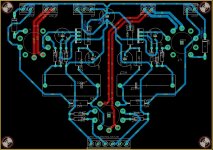
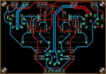
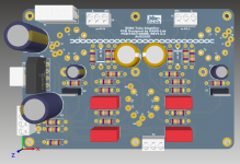
I've attached 2 variations, both have pretty much the same component layout.
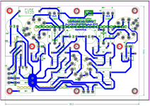
One has all routing on the bottom except 2 heaters.
The other has B+ and ground on the top side.
A few high level questions--
1) Are there any glaring issues with regards to a specific components placement or route?
2) Ground -- did I implement the star ground correctly? Is it preferred on top or bottom? Should I add any ground planes/copper pours?
3) B+ and heaters -- better on top or bottom?
Lastly, if you can recommend a USA business that is easy to deal with for small quantities, that would be helpful too.
Thanks!!
I've done a short online course on Eagle and am attempting my first PCB layout.
My knowledge in circuit design and layout is the smallest increment above none at all, and I would appreciate your help!
I chose the RH84 because it's an easy circuit and I wanted to build one anyway.
The schematic can be found here: RH Amplifiers: RH84 amplifier - revision 2
The rectifier, main filter cap and choke/HV regulated will be offboard.
I've attached 2 variations, both have pretty much the same component layout.
One has all routing on the bottom except 2 heaters.
The other has B+ and ground on the top side.
A few high level questions--
1) Are there any glaring issues with regards to a specific components placement or route?
2) Ground -- did I implement the star ground correctly? Is it preferred on top or bottom? Should I add any ground planes/copper pours?
3) B+ and heaters -- better on top or bottom?
Lastly, if you can recommend a USA business that is easy to deal with for small quantities, that would be helpful too.
Thanks!!
Attachments
For 3 boards, 4pcb is best for larger sizes ($33 each up to 60 sq in), and Osh Park is best
for smaller boards ($5 per sq in for 3 pcs incl shipping).
For your first boards that have high voltage, I would stay away from ground pours
to avoid problems with voltage isolation.
Rather than a star ground, lay out each sub-circuit first with its own common node,
focusing on component placement. Then connect each of the sub-circuit commons back
to the supply common. This will also give better routing.
Last edited:
I've made Osh Park small pcbs for less than $1 total, for three, shipped. Try to find that elsewhere.
It's by size. They're great, high quality, and made in USA. They can also do 4 layers or 2 oz copper.
It's by size. They're great, high quality, and made in USA. They can also do 4 layers or 2 oz copper.
Last edited:
Thanks for the info so far.
Which variation here is preferred, the one with B+ and GND on the top layer or the one with all on the bottom?
rayma, is the attached what you meant by the grounding?
The B+ decoupling cap negative is where all the grounds tie back to.
The branches (from each side) are for:
- 100uF, LM317 and 27R (EL84 ~CCS) and 470K
- input, 1M, 240R
- 10uF cap
Attachments

Hi all,
I've done a short online course on Eagle and am attempting my first PCB layout.
My knowledge in circuit design and layout is the smallest increment above none at all, and I would appreciate your help!
I chose the RH84 because it's an easy circuit and I wanted to build one anyway.
The schematic can be found here: RH Amplifiers: RH84 amplifier - revision 2
The rectifier, main filter cap and choke/HV regulated will be offboard.
I've attached 2 variations, both have pretty much the same component layout.
One has all routing on the bottom except 2 heaters.
The other has B+ and ground on the top side.
A few high level questions--
1) Are there any glaring issues with regards to a specific components placement or route?
2) Ground -- did I implement the star ground correctly? Is it preferred on top or bottom? Should I add any ground planes/copper pours?
3) B+ and heaters -- better on top or bottom?
Lastly, if you can recommend a USA business that is easy to deal with for small quantities, that would be helpful too.
Thanks!!
Nice job for first time- Eagle is powerful stuff- good to start Big
Prefer Design #1 keeping heaters underground 'cuz they're AC. Watch your hi current heater trace thick's tho.. Found this cool online calc-
Blocked
Use Elecrow (Chicoms) for production... no hazing, please!
6- 25 sq in double side 1 oz boards for $25 + $21 shipping. They are good people to work with- IMO. Been sending them my RS-274 projects for 5 years now-
Jim
I would turn the coupling caps vertical (place on either side of the 12AT7),
and move the plate Rs and decoupling Cs down close to the tube.
Keep the commons of each sub-circuit incl decoupling caps all close tied together,
and run one ground trace per channel up to the supply common.
If starting over, I'd have the 12AT7 in between the output tubes, and make the board
more rectangular.
Last edited:
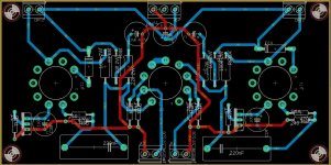
Thanks for the feedback... here is a different layout, which I think addresses most of that.
In this case, it was easiest to put GND on the top layer.
To simplify routing, I'll keep the heaters off board and add 2 pads next to each tube and solder twisted wires directly.
Any thoughts on this one?
In this case, it was easiest to put GND on the top layer.
To simplify routing, I'll keep the heaters off board and add 2 pads next to each tube and solder twisted wires directly.
Any thoughts on this one?
Attachments
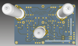
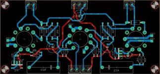
Another RH84 se amplifier
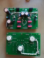
Here is my version of RH84, you can inspire from my layout or you can order my board from pcbway, i shared the project there for who wants to build it.
Is not the best layout but works pretty good for my tastes
RH84 Single ended amplifier - Share Project - PCBWay
Best regards,
DANO
Here is my version of RH84, you can inspire from my layout or you can order my board from pcbway, i shared the project there for who wants to build it.
Is not the best layout but works pretty good for my tastes
RH84 Single ended amplifier - Share Project - PCBWay
Best regards,
DANO
Attachments
OSH Park is incredibly expensive when you compare them to pcbway.
PCBWAY is expensive compared to JLCPCB.
This is the latest version.... appreciate any critical feedback here.
Thanks!
Better, it may be hard to clean it up much more.

hey knauf1919. I really like how you did the ground signal there along the perimeter. My layout is more in-line with what I'm planning for the chassis, but nonetheless I'd be happy to get those Gerber's for future reference. My email address is my alias here [at] gmail.com
Thanks!
Thanks!
Use 2oz copper board option, if possible.
Jim
The cost difference between 1 and 2 is substantial - just make the traces wider if you need to 🙂
PCBWAY is expensive compared to JLCPCB.
Very much so, but the OP wanted a fab based in the USA.
'The cost difference between 1 and 2 is substantial - just make the traces wider if you need to'
Concerned about B+ and GND trace widths- I'd increase those at least 50%
Not sure why the Digikey Trace width Calculator link shows as 'blocked' in my last post-
Digikey is well known electronic supplier in US for years- maybe 'cuz they don't advertise on this site- IDK.
Jim
Concerned about B+ and GND trace widths- I'd increase those at least 50%
Not sure why the Digikey Trace width Calculator link shows as 'blocked' in my last post-
Digikey is well known electronic supplier in US for years- maybe 'cuz they don't advertise on this site- IDK.
Jim
Last edited:
It costs nothing to leave copper on a pcb.
Make power and output tracks as thick as possible.
If possible I often run a track on both layers to double its current capacity.
Make power and output tracks as thick as possible.
If possible I often run a track on both layers to double its current capacity.
- Home
- Amplifiers
- Tubes / Valves
- First try at PCB layout (RH84 amp)