Hey everyone, this community is awesome. I'm learning a ton reading through the forums. One thing I haven't come across yet, is how to handle soldering two "output" wires to one binding post terminal. I've scoured the web, looking for videos or walkthroughs documenting how to handle the situation, but haven't found anything and am admittedly clueless. I'm attempting my first ever soldering with my first ever amp build on the 500ASP, with ghentaudio GK-ASP-MX case kit. I have one xlr input and a single pair of binding post outputs. The wiring harness that comes with the GK-ASP-MX has a jst signal cable with two red wires and two black wires. I'm assuming that I just solder both black wires to the black terminal and both red wires to the red terminal, but I don't want to fry my board or my house 🙂 If this is the method, what's the benefit of two wires per terminal (I see most builds online to only have one per terminal)? Is this required for "balanced" output? It seems that if you munge it all together in the same terminal, you're providing the same thing as one, maybe fatter wire, but I'm sure I'm missing something.
Thank you!
Robbie
Thank you!
Robbie
Looking at photo "9 of 10" from your link, yes, it appears you just double the black and reds to their respective posts.
Your guess is absolutely correct, it's using two strands in lieu of a bigger wire.
Your guess is absolutely correct, it's using two strands in lieu of a bigger wire.
Grounding
Hey all,
I have three wires all wanting to be grounded (picture of the wires/connections in question attached). The wiring harness provided with Ghent's case kit has a yellow/green wire intended to connect to a silver screw on the chassis with a loop on one end, and the IEC socket with a spade on the other. The kit-provided, ground wire for the board's AC connector also has a spade on the end (black in the picture). A third wire, from the XLR signal line is looking for ground as well (light grey). The confusing part to me, is why would I be provided two different wires in the same kit, knowing that there's only one terminal? I intend to somehow join these three wires, likely removing the second spade connector and stuffing all under the silver screw's bolt on the chassis. Is there a best practice when wiring multiple lines to ground?
Thank you,
Robbie
Attachments
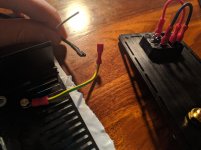
It's actually because of the onboard connector where the max. output current of the module means you need two pins to stay within the approved ratings 🙂Your guess is absolutely correct, it's using two strands in lieu of a bigger wire.
Yes. All three ground connections (mains inlet, module and XLR pin 1) need to "meet" at the ground screw that goes into the case (and only there) to avoid loops.Is there a best practice when wiring multiple lines to ground?
Looks to me like the black wire, the module's juice input, would want to connect to the neutral side of the DPST power switch on the IEC.
May just be me, but I get worried when folks confuse mains-Earth with mains-neutral -- you can defeat the whole purpose AND COST of that mandated third wire .. 🙁
The screw securing your Earth connection to the chassis looks a little short of engagement, too. Are you sure you have the correct screw, and the star lockwasher is properly located?
Cheers
Last edited:
Nisbeth:
Thank you for your responses. The idea that we need two skinny wires/pins to carry a load too large for either makes perfect sense. Your confirmation and reasoning for having the ground leads "meet" at the ground screw is great, as well. I like how your avatar depicts a typical form 🙂
Rick PA Stadel:
The screw securing my Earth connection to the chassis looks a little short, because I haven't tightened it down yet. I was just getting things in place and wanted the ability to swivel the yellow/green cable. As for the black wire, I actually have two black wires and a red wire providing juice to the module. I understand where the live and neutral go. I also understand that the third goes to ground, I just wasn't sure of the best approach. My questions are terribly green, I know 😀... but, had I followed your advice and plugged my ground into the IEC's neutral power, I might have had something real to worry about 😱
I intend to somehow join these three wires, likely removing the second spade connector
and stuffing all under the silver screw's bolt on the chassis. Is there a best practice when
wiring multiple lines to ground?
The IEC safety ground wire (green or green/yellow) is always connected alone to the chassis
near the IEC socket. Never connect other ground wires to that same point. Be sure to remove
all materials that would interfere with a good electrical connection (anodizing, paint, etc.).
In a chassis of multiple pieces that are each painted or anodized, all the parts should be electrically
connected together with jumper wires of the same size as the IEC wire, again with the paint or
anodization removed at each connection.
For other wires, up to two lugged wires may be connected to a single bolt. More than that can cause
the connection be unreliable. Don't try to crimp two wires into one lug, since that is also unreliable.
Last edited:
There is a discrepancy in advice on how to manage the 3 grounds, between posters 6 and 9.
Have people been using both or different methods with equal success?
Rayma, what is the reason you don’t want to have multiple grounds at this point(Star ground?)
Thanks
Have people been using both or different methods with equal success?
Rayma, what is the reason you don’t want to have multiple grounds at this point(Star ground?)
Thanks
- Home
- Amplifiers
- Class D
- First timer : balanced binding posts