it honestly looks pretty alright how it is. this is not for an audiophile. my ears get used to a speakers sound signiture and it never bothers me much. my main goal is to get it below 40hz. i know im making a lot of compromises for that. it wont ever need to be loud. 75db would be plenty of max volume i think. my parts are already ordered and a big part of this will be taking pride in my own design.
The lump is the bass drivers output rising as you come away from the bass port frequency. I can't think of an easy way to level it out much but I will take a look.
Poly fill will damp the port response hence the very low frequency lump would most likely flatten out a bit as the port Q would be reduced. Probably won't affect the second peak much it might even make it slightly worse as poly fill reduces the speed of sound in the box hence the walls look like they are further away (it take longer to reach them) and hence it makes the box look bigger.
Poly fill will damp the port response hence the very low frequency lump would most likely flatten out a bit as the port Q would be reduced. Probably won't affect the second peak much it might even make it slightly worse as poly fill reduces the speed of sound in the box hence the walls look like they are further away (it take longer to reach them) and hence it makes the box look bigger.
OK, in line with your fairly rough and ready approach to the response, I have come up with a very cheap and easily modifiable adjustment to reduce the second peak. If once built you find you have a bass problem sometimes described as one note bass as the peak emphasises bass in one region you could try the following mod.
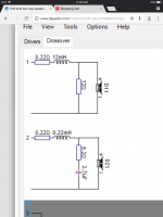
A fairly large value resistor in parallel with the bass drivers will dampen the bass driver resonance Q and hence flatten out the response in this region. It looks to me like 15R would be a suitable value but if you wanted a bit more of a peak you could go up say 22R or if you find the bass is over powering you could go down (I wouldn't go below 10R though as the load on the amplifier will start to get quite high).
A 5W wire wound resistor would be fine in this application if you are not planning to use the speakers for parties (and if you are just be aware the resistor might get very hot, its extremely unlikely to fail)
Attachments
if you dont see an easy fix to it, it satisfies my goals. like i said my ears are not a fine tuned instrument. doing informal off the internet test i can bearly hear a 6db difference in output of a single frequency, so combine that with listening to all the stuff going on in an audio track, and im guessing ill never know the difference. thanks again for your time and work, really appreciated.
yup. i just noticed i put the wrong inductor size in my drawing. i ordered a 12mh not a 14mh. sorry about that. i’ll definitely look into putting a resister in parallel with it. does the order of the two matter?
Yes heavily stuff the smaller enclosure (don't go mad though the air does need to be able to move) and if you can make it bigger all the better. Maximally flat (Q.707) is at 6L, this is impractical in your design as it would use to much of the bass enclosure but any extra volume would help.
do you think that 12mh inductor will make much difference compared to the 14mh? cant believe i made that mistake ive been going over this thing for over a week now.
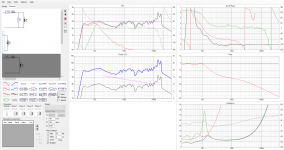
The resistor wants to go after the inductor next to the speaker as shown as it forms a bit of an LR filter with the inductor as well as adjusting Q. It performs much more effectively in this location.
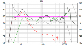
Plots below 12mH no resistor and 12mH 15R after inductor and 10R after inductor. The 10R version shows the impedance dropping to 3.5R at low frequencies so will place quite a load on the amplifier if you play it loud.
Plots below 12mH no resistor and 12mH 15R after inductor and 10R after inductor. The 10R version shows the impedance dropping to 3.5R at low frequencies so will place quite a load on the amplifier if you play it loud.
Attachments

this is fantastic, thanks so much. itll be awhile before i get to build it in a couple weeks, but ill put up pictures. im sure its gonna sound great for what i want. thanks again.
I hope it sounds good for you. If so sit back and enjoy.
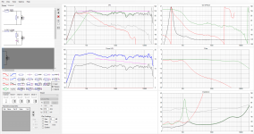
However if you find the top end is a bit harsh, which some full ranges can sound, you could tame it with a hi frequency filter. This will cost a bit more in parts as you will need a L C R solution. The L wants to be air cored and of fairly low resistance (I have simulated 0.22R but you could get away with a bit higher). The C should ideally be polypropylene but a cheap electrolytic would let you know if the approach was going to work (they can add a bit of distortion and change over time as they dry out but that is many years)
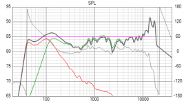
I have shown one below you can see how it reduces the peak at the top end and lowers the mid range, this will give you more apparent bass signal.
You can also see how bass resistor reduces the impedance at low frequency (bottom left) I have put a 12R in this circuit to provide another example.
However if you find the top end is a bit harsh, which some full ranges can sound, you could tame it with a hi frequency filter. This will cost a bit more in parts as you will need a L C R solution. The L wants to be air cored and of fairly low resistance (I have simulated 0.22R but you could get away with a bit higher). The C should ideally be polypropylene but a cheap electrolytic would let you know if the approach was going to work (they can add a bit of distortion and change over time as they dry out but that is many years)
I have shown one below you can see how it reduces the peak at the top end and lowers the mid range, this will give you more apparent bass signal.
You can also see how bass resistor reduces the impedance at low frequency (bottom left) I have put a 12R in this circuit to provide another example.
Attachments
are these the components i would need for that last simulation you posted? if so ill probably do that. seems silly to go to all this work and not spend a few extra bucks. also, this is the amp i got for the project. suitable?
Dayton Audio DTA-120 Class T Mini Amplifier 60 WPC
Dayton Audio DTA-120 Class T Mini Amplifier 60 WPC
Attachments
Last edited:
Yes, those are the components used in the sim.
The amplifier you posted looks fine for this application so long as you keep the volume reasonable. The bass impedance drops to arround 3.5 R and this will draw quite a lot of current at high volumes. If you crank it up too much it will most likey cut out as the overcurrent trip will go.
The amplifier you posted looks fine for this application so long as you keep the volume reasonable. The bass impedance drops to arround 3.5 R and this will draw quite a lot of current at high volumes. If you crank it up too much it will most likey cut out as the overcurrent trip will go.
use 4 of the 3" full range in the towers and a sub for deep bass
or 4 to 8 of the 4" woofers with a tweeter crossed at 5 khz
45 to 55 hz can be had as the woofer resonance creates a high impedance there
place a resistor of 8 -15 ohms in series with each driver to peak the bass in this range
two drivers plus 2 8 ohm resistors yeilds 8 ohm load off the 12 - 15mh coil.
i did this with a nuance 3CL speaker ( 2 - 8" drivers ) to get great bass down to 35hz
Last edited:
stocktrader200, these have to fit in a large drawer when not in use, for the spouse aproval factor. the dimensions are set in stone. i had thought about a small sub and two small sealed full range, but i just kept getting drawn to this idea. i liked the challenge of trying to get it to work in a small space, and all my parts are already on the way. i do appreciate your suggestions though. these are so i dont have to watch chick flicks on the tv speakers anymore. its amazing how a movie can be more interesting with decent speakers. for real music and movies ive got a pair of pretty nice, full sized energy brand speakers and big sub in my basement.
- Status
- Not open for further replies.
- Home
- Loudspeakers
- Multi-Way
- first time two way speaker. please look over and give advice.