Hi dear diyaudio members, hope you'll help me.
I'm trying to build a mic preamp based on INA217 chip. It's a pretty standard preamp (did only few modifications to the original schematic that I found in spec sheet).
This is original schematic:
I added polarity inverse switch and pad -20dB switch.
Currently i'm working on a PCB in Eagle, so my question is about wire width. I'm planning to do a photo procedure for pcb, so what is the wire width with which I could work? Now it's set up to 0.016mm.
This is my current version of PCB (on edges you could see I started rewiring with wider lines).
Thank you,
Petar.
I'm trying to build a mic preamp based on INA217 chip. It's a pretty standard preamp (did only few modifications to the original schematic that I found in spec sheet).
This is original schematic:
An externally hosted image should be here but it was not working when we last tested it.
I added polarity inverse switch and pad -20dB switch.
Currently i'm working on a PCB in Eagle, so my question is about wire width. I'm planning to do a photo procedure for pcb, so what is the wire width with which I could work? Now it's set up to 0.016mm.
This is my current version of PCB (on edges you could see I started rewiring with wider lines).
An externally hosted image should be here but it was not working when we last tested it.
Thank you,
Petar.
Hi Petar
Thicker the better !
You might also consider implementing some kind of ground-plane...
...or well considered 0v earthing paths.
R1 & R2 are best, VERY well matched.
Also R4 & R5
C1 & C2 I would dump the polarised caps; and go for a 10uF plastic type.
They are BIG...you will need much more room to fit them if you decide to do so...
...much better sound...VERY low signal loss & distortion from the low mic signal.
Also, no micro small 'voltage leaks' from the large 48v phantom power.
Also, the 1N4148 diodes are not really needed...
...and may, if omitted, result in a marginally better noise performance.
I guess you're doing other boards, for the 48 phantom & dual 15v PSU's.
Cheers.
Si.
Last edited:
Hi there, bit of a stupid question but I'm trying my best to learn without school at the moment. It looks like R4 and R5 are only there to serve as pull-down resistors to the diodes; assuming they were removed and the end user (me, hopefully) took extra care not to damage the rest of the device, would they still be necessary? I don't see a need for them otherwise, unless the signal itself needs to be attenuated (? guessing that is what the resistors would do) before it is amplified.
Either way, thanks for the original post. Looking forward to recording some interesting sounds with this pre.
Either way, thanks for the original post. Looking forward to recording some interesting sounds with this pre.
I'm not familiar with the chip used, but my guess is that R4 and R5 are bias resistors for the INA217. The diodes appear to be for over-voltage clamping, so normally will be reverse biased and so not conducting.
Diodes are protection.
R4/R5 in conjunction with C1/C2 determine form input high pass filter. R4/R5 also effectively set input impedance.
Virtually all powered microphones also have blocking capacitors for isolation. These are effectively in series with mic-pre caps, and raise corner frequency of high pass filter.
This is case where bigger is better. Phase/transient response of LF signals will be badly smeared by using 10uf instead of 47uf:
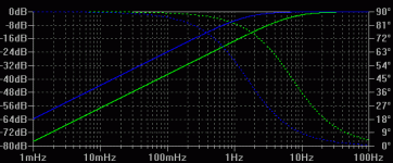
Frequency/Phase for 10u v 47u with 2200ohm resistor:

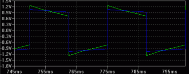
The -3dB points may seem quite low relative to music signals, but this is what these two filters do to 40Hz square wave:

Bigger input capacitor reduces waveform remodeling.
Regards,
Andrew
R4/R5 in conjunction with C1/C2 determine form input high pass filter. R4/R5 also effectively set input impedance.
Virtually all powered microphones also have blocking capacitors for isolation. These are effectively in series with mic-pre caps, and raise corner frequency of high pass filter.
This is case where bigger is better. Phase/transient response of LF signals will be badly smeared by using 10uf instead of 47uf:
Frequency/Phase for 10u v 47u with 2200ohm resistor:

The -3dB points may seem quite low relative to music signals, but this is what these two filters do to 40Hz square wave:

Bigger input capacitor reduces waveform remodeling.
Regards,
Andrew
Read note 2 under Absolute Maximum Ratings in the INA217 datasheet:
- Input terminals are diode-clamped to the power-supply
rails. Input signals that can swing more than 0.5V
beyond the supply rails should be current limited to 10mA
or less.
You have no input current limiting in that schematic and 48V phantom power switching will generate large voltage pulses at the INA217 input terminals, so the input clamping diodes are essential.
Some mic pres use back to back zeners to protect the inputs.
See text under fig.2 on this page 48V Phantom Feed Supply for Microphones
Even with that level of protection I still managed to pop a 5532 in a mic pre yesterday, but I was being stupid with it !
I have built several of these mic pre"s using the INA217 so ill just post a few of my observations and experiences .....
The 4148 diodes can be omitted if you allways remember never to plug in a mic with phantom power already turned on , they are protection diodes for hot plugging .....
r4 & r5 set the input impedance , R1 & R2 are for current limiting for the phantom power and should be well matched from best CMRR performance .....
C1 & C2 are DC phantom blockers and I had good performance using good quality Polarized cap though I used 100uF caps as opposed to 47uf and bypassed them with a 0.1uf film cap .....
If you want to go minimalistic you can also drop the OPA134 DC servo part of the circuit but you will have to add a output cap to the circuit , I used a 16v 470uF cap and put a 1k resistor to ground after the cap and had fairly good performance ......
I have several of these mic preamps in my home studio (both with all features and minimalistic) and they sound very good ......
Cheers
EXACTLY ! Minion !
Microphones should NEVER be 'hot plugged'
The diodes can be omitted.
& as said earlier, the phantom power resistors...
...MUST be well matched.
I'd bung in a couple of wire-wounds here, from a matched bunch.
( just my take ! )
Cheers.
Si.
I've had good results with 10uF input-caps in a similar situation...
...but hey...I just 'listen to 'em'...
...the sim & scope of course...'tell it how it is'.
- Status
- Not open for further replies.
- Home
- Design & Build
- Parts
- First time diy - mic pre