Thanks for all the detailed replies and I really appreciate it 🙂 . I should have included more details with my first posting. I am not actually building a new speaker from scratch. I owned a pair of 20 year old Monitor Audio MA700 and after reading some online articles & watching some Youtube videos, I thought of changing out the drivers and crossover to see if I can get a better sound using the existing box.
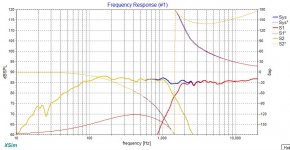
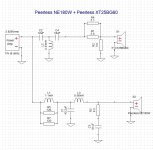
After checking the cabin volume, it seems Peerless NE180W-08(6.5") seems like a better fit. So now the final combination is, Peerless NE180W-08 (woofer) and Peerless XT25BG60-04 (Tweeter). I will attach as many graphs as I can get from XSim and hopefully there will be enough data to roughly assess the crossover result.
As you guys can tell I am REALLY new to this and until now there are still many things mentioned in there above discussion are still aliens to me. Hopefully I have not upset anyone with my ignorance.
Attachments
-
 Frequency Response.JPG95.6 KB · Views: 107
 -
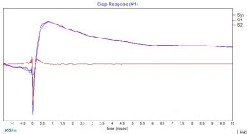 Step Response.JPG33.8 KB · Views: 57
 -
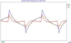 Square Wave Response.JPG40.5 KB · Views: 63
 -
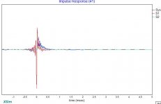 Impulse Resoponse.JPG30.2 KB · Views: 54
 -
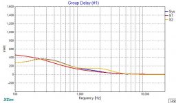 Group Delay.JPG60.4 KB · Views: 98
 -
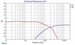 Electrical Response.JPG61.8 KB · Views: 101
 -
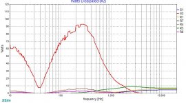 100 Watts Dissipated.JPG93.4 KB · Views: 120
 -
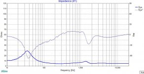
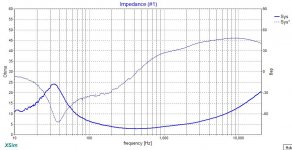 Impedence Response.JPG91.2 KB · Views: 104
James, there are quite a few oddities in your crossover that need dealing with. A 43uF in a tweeter series circuit is effectively a dead short, or close to it. The 0.33mH is also a dead short, so effectively what you have is a 10uF to ground with a 43uF in series, to the amplifier this presents a very low load at high frequencies. It also serves absolutely no purpose. A third order crossover will typically (but not always) have tweeter series cap ratios much closer, not 43:1.
Your tweeter L-pad is completely off. Typically the values will sum to about the same impedance as the tweeter. So for a 4-ohm tweeter, you should have (as only one example, of several possibilities) a 2 ohm series resistor with a 4 ohm shunt. the values look very badly off - which means the tweeter is barely getting enough signal. And yet I can see a lot of output in the graph, so where did you get the original driver response graphs from?
Similar is the padding in the woofer circuit just before the driver. We never drop woofer sensitivity by using resistors, just adjust the tweeter L-pad to match them. That is why you are requiring massive power from the amp, some due to the impedance and some due to series padding of the woofer. There are some issues with woofer circuit values but those can be solved relatively easily. You should be able to manage most woofers at 2kHz and above with a simple second order circuit plus a zobel, unless it's a metal cone driver.
I would suggest starting from scratch. Post the DXO files here, so one of us can take a look. Also do indicate where you got the response curves from. If you don't yet have the drivers and are using manufacturer graphs, you will also need to add in the driver time delay and baffle step, among other things.
Lets help him get the on-axis response right.
Why? The on-axis SPL response is not the primary thing to get "right". Really, to learn this stuff it is much more useful to understand what to look at, and how.
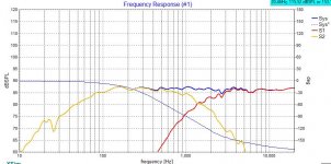
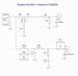
Oh MY Goodness.....@Sangram, you are really amazing! You spotted the most fatal mistake in my crossover design, my ZMA file for the tweeter is wrong. I must have keyed in a wrong Y-axis value when using FPGraphTracer. Using the right ZMA file and following those tips you gave in your reply, I managed to get a new crossover design with better results (I hope so). For now I will just upload the Frequency Response Curve, Impedance Curve and the design diagram. Please let me know what all of you think about the new design. Thanks for all the help thus far.