Spoke too soon.. I used the pcb pins but never connected them ha! 😛
Ok, after I fixed that I can confirm I do hear the input at a lower volume (but do clearly hear it). However still only getting left channel.
So right channel is failing around U1?
Ok, after I fixed that I can confirm I do hear the input at a lower volume (but do clearly hear it). However still only getting left channel.
So right channel is failing around U1?
Ok I did this. I removed U2 and used some spare pcb pins to link pin 3 and 1, and then pin 5 and 7 on the socket.
I could not hear anything. I turned it way up on my speakers and still could not hear anything from the turntable. I did however hear a loud hum on the right channel.
Btw those resistors I did check and seemed to be the correct values. I was able to check them without anything out.
It would seem there is a problem around U1 and yet I'm not convinced. I just wonder if you have more than one problem here.
Lets try and get some output from the faulty channel by cross connecting the opamps.
Which 'side' of the opamp is left and which is right ? I'm assuming pins 1,2 and 3 are 'left', the good side.
So with U2 still removed, connect pin 1 of U1 to pins 1 and 7 of U2. That will feed the known good output into both channels. You should get identical audio from both channels.
If that is OK then we look next at the faulty side of U1. Its very difficult without actually seeing it all and without using test equipment such as a signal generator and scope.
However... U1. Can you measure and record the exact DC voltages you are seeing on pins 1,2,3 and pins 5,6 and 7. Do this with no music playing, The voltages will be very small, in the millivolt region, but lets compare them one channel to the other.
Pin1=
Pin2=
Pin3=
Pin5=
Pin6=
Pin76=
To clarify.. should I be doing this with the pin connections 1-3 and 5-7 still on the U2? Or undo those and then do U1 pin 1 to U2 pins 1 and 7.
I did the latter and was getting nothing with a record playing, just a buzz/pop.
Something seems wrong though, because I am getting almost 15 VDC on many of the pins
I did the latter and was getting nothing with a record playing, just a buzz/pop.
Something seems wrong though, because I am getting almost 15 VDC on many of the pins
It would seem there is a problem around U1 and yet I'm not convinced. I just wonder if you have more than one problem here.
Lets try and get some output from the faulty channel by cross connecting the opamps.
Which 'side' of the opamp is left and which is right ? I'm assuming pins 1,2 and 3 are 'left', the good side.
So with U2 still removed, connect pin 1 of U1 to pins 1 and 7 of U2. That will feed the known good output into both channels. You should get identical audio from both channels.
If that is OK then we look next at the faulty side of U1. Its very difficult without actually seeing it all and without using test equipment such as a signal generator and scope.
However... U1. Can you measure and record the exact DC voltages you are seeing on pins 1,2,3 and pins 5,6 and 7. Do this with no music playing, The voltages will be very small, in the millivolt region, but lets compare them one channel to the other.
Pin1=
Pin2=
Pin3=
Pin5=
Pin6=
Pin76=
Have the circuit in front of you and try and follow the logic 🙂
With both opamps fitted, all the pins apart from the power supply should be at zero.
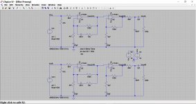
Here's your circuit:

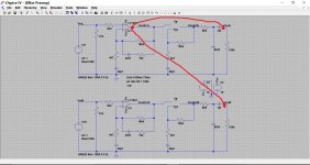
Now we remove U2 and feed the known good output into both pins 1 and 7 of where U2 was.

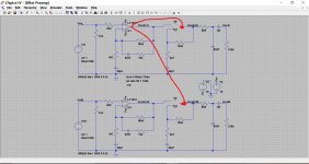
This should give identical output from both channels proving that from U2 output pins to the outside world is OK. The green trace is perfectly overlaid by the blue which is why its not visible.

With both opamps fitted, all the pins apart from the power supply should be at zero.
Here's your circuit:
Now we remove U2 and feed the known good output into both pins 1 and 7 of where U2 was.
This should give identical output from both channels proving that from U2 output pins to the outside world is OK. The green trace is perfectly overlaid by the blue which is why its not visible.
@Mooly I just got a chance to test this again and here's what I found.
So before I said I was getting high voltages across many of the pins. I decided what the hell, I'll try dipping the whole box in 99.9% isopropyl alcohol and letting it evaporate out. After I did that, only the power pins (4 and 8) were getting the 15V, and the rest were properly getting 0 (or a few mV).
This had happened before when I first built it, and I did the same thing which fixed it. I'm glad it worked but it's a little disconcerting that I can't pinpoint what was wrong!
Ok, then I removed U2 and hooked pin 1 of U1 to both pins 1 and 7 of U2... and still only left channel playing 🙁
Have the circuit in front of you and try and follow the logic 🙂
With both opamps fitted, all the pins apart from the power supply should be at zero.
Here's your circuit:
View attachment 544865
Now we remove U2 and feed the known good output into both pins 1 and 7 of where U2 was.
View attachment 544866
This should give identical output from both channels proving that from U2 output pins to the outside world is OK. The green trace is perfectly overlaid by the blue which is why its not visible.
View attachment 544867
This is sounding more and more like you have more than one problem, and that these problems could be physical issues rather than component problems.
Lets work with this:
That proves beyond doubt that you have a definite problem with the signal path from the right hand output socket to U2. There has to be a break between these two arrowed points. Now you may have other problems as well, but this one is definite.
(You say you have proved (earlier post) that the leads and amplifier are OK by you swapping leads around)
So connect a bit of wire to either pin 1 or pin 7 (doesn't matter which because both are linked) and dab that wire on to the output socket. You must get audio doing that. Then move the wire back along the signal path dabbing it on the cap and series resistor.
Lets work with this:
Ok, then I removed U2 and hooked pin 1 of U1 to both pins 1 and 7 of U2... and still only left channel playing
That proves beyond doubt that you have a definite problem with the signal path from the right hand output socket to U2. There has to be a break between these two arrowed points. Now you may have other problems as well, but this one is definite.
(You say you have proved (earlier post) that the leads and amplifier are OK by you swapping leads around)
So connect a bit of wire to either pin 1 or pin 7 (doesn't matter which because both are linked) and dab that wire on to the output socket. You must get audio doing that. Then move the wire back along the signal path dabbing it on the cap and series resistor.
Attachments

So connect a bit of wire to either pin 1 or pin 7 (doesn't matter which because both are linked) and dab that wire on to the output socket. You must get audio doing that. Then move the wire back along the signal path dabbing it on the cap and series resistor.
1)
Ok when you say they are linked, you mean because I should still have the U1pin1 => U2pin1 + U2pin7 connection?
2)
so we know the right channel from U2 to the output is broken, but how do we know its not also broken from input to U2 ?
1) Yes, its still set up as before (when you had this).
2) There may well be other problems with the amp, but still having no right hand output when its connected as above proves beyond doubt there is a problem with the feed from U2 output to the outside world.
Ok, then I removed U2 and hooked pin 1 of U1 to both pins 1 and 7 of U2... and still only left channel playing
2) There may well be other problems with the amp, but still having no right hand output when its connected as above proves beyond doubt there is a problem with the feed from U2 output to the outside world.
Ok, I connected back U1 pin 1 to U2 pin 1+7.
Then I connected U2 pin 1 to the output socket and yes I did hear both channels finally. Interestingly, if I touch it against the output pin on the board, it doesn't work. Only if I touch the hot tab on the socket do I get both channels. I think I have to redo the soldering there as maybe I shorted it.
Tapping the wire against the right channel output pin on the board does nothing.. so anything before that point does nothing as well (resistors etc.).
So I believe I can resolder the right channel on the socket and see what happens. Does this mean it's possible U2 was fine all along?
1) Yes, its still set up as before (when you had this).
2) There may well be other problems with the amp, but still having no right hand output when its connected as above proves beyond doubt there is a problem with the feed from U2 output to the outside world.
U2 could well be OK but we need to work back to prove it all.
Work with what we know to be definite issues 🙂 You've got sound from both outputs now, so we know there must be either a problem with the continuity from the socket back to U2, or that there is a short somewhere on those components that's killing the audio.
Fix that one issue first. You need sound from both outputs when U2 is removed, and when pins 1 and 7 are linked and connected back to U1 (just as you have it now)
Ok, I resoldered the socket connections for the right channel.
With U1pin1 to U2pin1+7:
- getting input on both channels, although left about 3-6dB louder.
- when I tap a wire from U2pin1 to the output socket, right channel becomes about 3-6db louder than left. Same things happens when I tap it against output pin for right channel (so I guess the resoldering did fix something). Same thing if I tap the wire against a resistor near the right channel output pin.
Then I undid the connections and installed U2 back:
- getting input on both channels, but left is MUCH louder than right (~40dB difference). Actually I believe the audio coming through the right channel is simply the noise level getting amplified by U2. I don't think any audio is making it through right channel.
U2 could well be OK but we need to work back to prove it all.
Work with what we know to be definite issues 🙂 You've got sound from both outputs now, so we know there must be either a problem with the continuity from the socket back to U2, or that there is a short somewhere on those components that's killing the audio.
Fix that one issue first. You need sound from both outputs when U2 is removed, and when pins 1 and 7 are linked and connected back to U1 (just as you have it now)
Last edited:
I'm still here 🙂
Going back to what I said earlier, when you connect the output of U2 (which is still removed and pins 1 and 7 linked) to the output sockets you should have identical audio on both channels. If it is not then there has to be yet another issue but this time external to the preamp.
Just think about the logic of that. We are feeding the same signal (coming from the same point on the board) to the left and right sockets directly. So the audio you hear has to be the same on both channels.
Now... if you mean it is 3-6 db different with the 820 ohm and 1uf coupling cap in place, and that the audio is now passing through those (so not directly linked with a piece of wire from the sockets to U2) then there has to be a simple problem with either the connections of those parts or the value of them... such as the 820 ohm being something else on one channel.
I'll have more time tomorrow if you are stuck 🙂 but try and look at the circuit and apply logic to what we are doing. We are attempting to prove/disprove faults by linking out complete sections at a time and feeding the same signal to left and right.
Ok, with U2 removed and the wire links (U1pin1 to U2pin1+7):
I am definitely getting ~2dB difference between L+R channels. Under normal stereo conditions this would make sense.. but here we are sending the 'L' channel to both L+R output correct? So you're saying they should be identical - but they're not, hmm.. I can't seem to understand how that could be happening.
With this same setup, if I take a wire from U2pin1 (or 7, they are linked), and tap the R channel output socket, the R channel output jumps to ~3dB higher than the L.
So... to recap.
Here is your preamp. With U2 removed and with wire links as shown you should be getting equal volume from both channels.
If you have it connected as per the middle diagram (which means feeding to the 'socket side' of the 1uf, exactly as drawn) then you have to have identical output from both sides.
As proof that you have wired it correctly for this test, you should be able to measure a dead short (0.00 on DVM on low resistance range) between the centre pin of left and right output terminals.
If you still hear a difference in level then the cause for that must be external to the preamp.
Does that make sense ? If your not sure or don't agree then say so 🙂
I believe I had it connected as shown in your last diagram... that would be with U1pin1 to U2pin1+7 correct?
If I'm understanding correctly, the middle diagram is showing U1pin1 going straight to the L and R socket? That I have not tried yet, but.. I can't possibly see how that would NOT result in identical outputs on L+R !
If I'm understanding correctly, the middle diagram is showing U1pin1 going straight to the L and R socket? That I have not tried yet, but.. I can't possibly see how that would NOT result in identical outputs on L+R !
If you have it connected as per the middle diagram (which means feeding to the 'socket side' of the 1uf, exactly as drawn) then you have to have identical output from both sides.
As proof that you have wired it correctly for this test, you should be able to measure a dead short (0.00 on DVM on low resistance range) between the centre pin of left and right output terminals.
If you still hear a difference in level then the cause for that must be external to the preamp.
Does that make sense ? If your not sure or don't agree then say so 🙂
Connected as the in the last diagram could give non identical output on each channel if there were a difference (such as a construction error or wrong value part) in the components to the right of the connection point. That's what we need to prove.
Connected as per the middle diagram has to give equal output on both channels. That proves that your listening setup is giving equal loudness to both channels... it has to in that configuration.
Connected as per the middle diagram has to give equal output on both channels. That proves that your listening setup is giving equal loudness to both channels... it has to in that configuration.
Ok, now I'm really confounded..
I set up as shown in middle diagram: no U2, U1pin1 going to both L+R sockets.
With this setup I'm still getting ~2-3dB higher on the L channel.
I ensured that the preamp gain levels on my interface are identical for L+R, so I really can't see what else could be causing the difference.
😕
I set up as shown in middle diagram: no U2, U1pin1 going to both L+R sockets.
With this setup I'm still getting ~2-3dB higher on the L channel.
I ensured that the preamp gain levels on my interface are identical for L+R, so I really can't see what else could be causing the difference.
😕
Connected as the in the last diagram could give non identical output on each channel if there were a difference (such as a construction error or wrong value part) in the components to the right of the connection point. That's what we need to prove.
Connected as per the middle diagram has to give equal output on both channels. That proves that your listening setup is giving equal loudness to both channels... it has to in that configuration.
There has to be the same signal at the sockets when wired as per the middle diagram.
Do a check. If you unplug the leads from the preamp to your main amplifier at the main amplifier end then you should be able to measure continuity (a dead short) between the centre pins of the two leads (L&R)
Do a check. If you unplug the leads from the preamp to your main amplifier at the main amplifier end then you should be able to measure continuity (a dead short) between the centre pins of the two leads (L&R)
- Status
- Not open for further replies.
- Home
- Amplifiers
- Chip Amps
- first time builder. Need help grounding this phono preamp