Can some body recommend me a simple tube amp design for someone who has never built one? I do have a working knowledge of basic electronics, science, and math. Can someone point me in the direct of a good book that would introduce me to the theory of amp tube design?
Morgan Jones' Valve Amplifiers is a very good introduction, but you'll have to either buy it or go borrow it from a library. Failing that, you could try the Radiotron Designers' Handbook, 4th Edition, but it is a much steeper learning curve (and makes for dryer reading 😉)
Here's one that is inexpensive to build and requires only a single tube per channel. At 3 watts it won't make your ears bleed but it would be a good intro.
The site gives you the schematic, a parts list and a pictoral layout.
http://www.lh-electric.4t.com/projects/tiny3w.htm
The site gives you the schematic, a parts list and a pictoral layout.
http://www.lh-electric.4t.com/projects/tiny3w.htm
Thanks Guys
Sherman and kmj these articles are exactly what I had in mind. audiousername the handbook is a monster. Thank goodness for high speed. This should be enough to get me started.
Sherman and kmj these articles are exactly what I had in mind. audiousername the handbook is a monster. Thank goodness for high speed. This should be enough to get me started.
Re: Thanks Guys
Remember, vacuum tubes are very forgiving devices and if you get your components and parameters within about 10% or so everything should work. Don't get hung up on nailing exactly 300 volts for B+ (for instance). 270 to 330 volts in most cases is close enough for government work.
Also remember that potentially lethal voltages exist in most tube circuits. Read the safety thread here and take precautions.
Good luck and have fun!
Jason Watts said:...This should be enough to get me started.
Remember, vacuum tubes are very forgiving devices and if you get your components and parameters within about 10% or so everything should work. Don't get hung up on nailing exactly 300 volts for B+ (for instance). 270 to 330 volts in most cases is close enough for government work.
Also remember that potentially lethal voltages exist in most tube circuits. Read the safety thread here and take precautions.
Good luck and have fun!
Do you have any tube parts, especially the iron (PT and OPTs)? That's where a lot of the expense is.Jason Watts said:Can some body recommend me a simple tube amp design for someone who has never built one?
It's easy to say 'built this, it's easy' but it's not much use spending money on parts you may not use again. Do you think, if you find the audible results positive, that you'd build a bigger/different amp? And if so, how much power do you think you'd need? I'm asking because it's easy to be shown a sub 3W SE amp to build that would be easy as a first project. But, if you think you'd need 15W later, than the OPT you bought for this project will be useless for another. just something to think about before you plunge in and spend the money on iron etc.
Check the page I've linked below. there are a number of SE and PP designs there. The Shisheido PP is good (I've built one very similar) and the 6EM7 design has a lot of potential as it's a really sweet tube.
http://www.the-planet.org/
Enjoy.
Tube Design
My real interest here is being introduced to tube theory. I wanted to a very simple amp with a very simple description of how each section or stage functioned. That is what I got. At the same time I was looking for some detailed theory for me to study. My intent is to build a simple amp from my own design. It is fairly simple to follow someone else’s wiring diagram or schematic. Doing this really doesn’t teach me too much about how it really works. I have some tubes in my parts pile in the garage. I will to look and see what I got. I already have a tube receiver in my system that has about 50 watts per channel. That is all I really need. I do plan on building two mono blocks in the near future that produces the same amount of power. I don’t like the tone controls on the receiver and would prefer all of the signal processing be performed digitally. At the same time I want to create to mono blocks simply for amplification purposes only. I will try to use some of the parts from my first amp on the two mono blocks. I hope to keep the pricier parts (like transformers) for the mono blocks.
My real interest here is being introduced to tube theory. I wanted to a very simple amp with a very simple description of how each section or stage functioned. That is what I got. At the same time I was looking for some detailed theory for me to study. My intent is to build a simple amp from my own design. It is fairly simple to follow someone else’s wiring diagram or schematic. Doing this really doesn’t teach me too much about how it really works. I have some tubes in my parts pile in the garage. I will to look and see what I got. I already have a tube receiver in my system that has about 50 watts per channel. That is all I really need. I do plan on building two mono blocks in the near future that produces the same amount of power. I don’t like the tone controls on the receiver and would prefer all of the signal processing be performed digitally. At the same time I want to create to mono blocks simply for amplification purposes only. I will try to use some of the parts from my first amp on the two mono blocks. I hope to keep the pricier parts (like transformers) for the mono blocks.
Re: Tube Design
Also read all of Tubecad.com , especially the Grounded Cathode Amplifier article. Clear and easy to understand.Jason Watts said:My real interest here is being introduced to tube theory. I wanted to a very simple amp with a very simple description of how each section or stage functioned.
7591A-P
I got to digging in my garage and found four 7591A-P tubes. Can someone direct me to a sample amplifier circuit that uses these tubes. Simple circuit I hope.
I got to digging in my garage and found four 7591A-P tubes. Can someone direct me to a sample amplifier circuit that uses these tubes. Simple circuit I hope.
Re: 7591A-P
Lots of stuff like old Scotts and Fishers used the 7591. It's a 6L6-ish tube and with some minor changes in some circuits, both could be used. Check the datasheet and this page for 7591 - 6L6 conversion info.Jason Watts said:I got to digging in my garage and found four 7591A-P tubes. Can someone direct me to a sample amplifier circuit that uses these tubes. Simple circuit I hope.
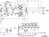
Here's a Fisher X101C schematic. Everything's there except the grid resistor for the first 12AX7 (not critical but 100k or so would do). Lines going off the page are just links to the other channel.
OPT is 6k6 a-a. I'd do a fullwave rectifier myself and ditch the doubler, but that's just my preference.
Not a bad sounding little amp.
OPT is 6k6 a-a. I'd do a fullwave rectifier myself and ditch the doubler, but that's just my preference.
Not a bad sounding little amp.
Attachments
Re: 7591A-P
Fisher 500C
http://www.fortunecity.com/tinpan/beegee/290/page4.html
dave
Jason Watts said:7591A-P
Fisher 500C
http://www.fortunecity.com/tinpan/beegee/290/page4.html
dave
Some Questions
I have some questions. I have chosen to build a 2 stage amplifier using 12AX7 dual triode tubes in the primary stage and 7591A pentodes in the secondary stage. I will use this simple triode amp design found at this link.
http://web.telia.com/~u85920178/begin/tube0.htm#aftrio
My question is if I wire both triodes in the 12AX7 in parallel. How will the anode voltage and grid voltage change? Will they be the same as one or will it double?
For the 2nd stage I will be using the same circuit found at the same link except it will be for the pentode amp. I will be using the same idea but I will be wiring two pentodes in parallel. How will the tube the anode and grid voltages change by doing so?
I will be attaching the AFout from the first stage directly to the AFin of the 2nd stage. Do I need the capacitor Cout form the triode amp and the capacitor Cin from the pentode amp or can I get buy with just one? I think am trying to say can I replace both with a single capacitor of equal value or will it be a different capacitance value?
I also robed output transformers from an old Fisher amp I hand laying around. When I removed it I made sure I new what wire come from where. Two of the wires were attached directly to the speaker out so one has to the ground and the other one is for the speaker. There were three other wires. One went to the HV and the other two was directly attached to the socket of a 12AX7. Those two came directly from each triode plate. Can I simply leave one of those wires open when I directly attach it to the pentode plate of the 2nd stage?
I will be building two of these amps and powering both from the same transformer. The transformer can supply .15 amps of current. I can get the voltage I need for the tubes from voltage multiplier circuits but can a transformer that produces .15 amps of current produce enough power to power two of these amps? A total of two 12AX7 tubes and four 7591A pentodes?
Re: Some Questions
Current will double voltages stay the same. Not a good idea to parallel sections if you can get away with it.
12AX7 is common, but not really great.
same... current doubles, the load you provide (ie OPT primary should halve)... you running the amp Single Ended?
Cout from the driver is the same cap as Cin to the output stage.
They should have been connected to the plates of the output tubes, not the 12AX7s. You imply a single-ended amp, the Fisher OPTs are (very very likely) push-pull transformers, and using them in an SE amp is a no-go or you need to add a parafeed choke to supply DC to the output stage.
no...
The 12AX7s typically draw 1 mA/section = 4 mA and typical 7591 is 75 + 15 mA/tube = 360 mA, to your amp needs about a 1/3 of an amp... i wouldn't use anything less than a trafo that could supply 1/2 an amp and that is really not enuff margin for my taste.
dave
Jason Watts said:My question is if I wire both triodes in the 12AX7 in parallel. How will the anode voltage and grid voltage change? Will they be the same as one or will it double?
Current will double voltages stay the same. Not a good idea to parallel sections if you can get away with it.
12AX7 is common, but not really great.
For the 2nd stage I will be using the same circuit found at the same link except it will be for the pentode amp. I will be using the same idea but I will be wiring two pentodes in parallel. How will the tube the anode and grid voltages change by doing so?
same... current doubles, the load you provide (ie OPT primary should halve)... you running the amp Single Ended?
I will be attaching the AFout from the first stage directly to the AFin of the 2nd stage. Do I need the capacitor Cout form the triode amp and the capacitor Cin from the pentode amp or can I get buy with just one? I think am trying to say can I replace both with a single capacitor of equal value or will it be a different capacitance value?
Cout from the driver is the same cap as Cin to the output stage.
I also robed output transformers from an old Fisher amp I hand laying around. When I removed it I made sure I new what wire come from where. Two of the wires were attached directly to the speaker out so one has to the ground and the other one is for the speaker. There were three other wires. One went to the HV and the other two was directly attached to the socket of a 12AX7. Those two came directly from each triode plate. Can I simply leave one of those wires open when I directly attach it to the pentode plate of the 2nd stage?
They should have been connected to the plates of the output tubes, not the 12AX7s. You imply a single-ended amp, the Fisher OPTs are (very very likely) push-pull transformers, and using them in an SE amp is a no-go or you need to add a parafeed choke to supply DC to the output stage.
I will be building two of these amps and powering both from the same transformer. The transformer can supply .15 amps of current. I can get the voltage I need for the tubes from voltage multiplier circuits but can a transformer that produces .15 amps of current produce enough power to power two of these amps? A total of two 12AX7 tubes and four 7591A pentodes?
no...
An externally hosted image should be here but it was not working when we last tested it.
The 12AX7s typically draw 1 mA/section = 4 mA and typical 7591 is 75 + 15 mA/tube = 360 mA, to your amp needs about a 1/3 of an amp... i wouldn't use anything less than a trafo that could supply 1/2 an amp and that is really not enuff margin for my taste.
dave
Sweet Amp- Simple design........
Go to http://audiotropic.netfirms.com/blurb1.html
I built this amp & it is excellent outperforming most amps I have owned. Get a RCA 5965 as it is a stellar performer in this amp. Want more than 6-watts? Just double up the 6V6s to parallel 6V6 for 10-12 watts out. If you use four 6V6GT per channel, the audio transformer should be 6000 ohm primary and about 30-watt size. A pair of audio transformers from a Sansui 1000A would be great.
I recommend the newer coin base GE 6V6GT. Do not try the old metal 6V6 tubes as they sounded rather poor. A poor tube can make or break an amp at times.
- Status
- Not open for further replies.
- Home
- Amplifiers
- Tubes / Valves
- First Time Amp