Hi there, i'm trying to make a L+R summer with LP with the least components possible, which also provides the original L and R reparate channels with HP.
Despite both circuits need some adjustment to get the -3dB point coincident, i sort of get what i want, but when i connect both things in parallel to the AC generator the filters go mad. It may be an awfull abomination but this is as far as i got, is there an easy way to isolate both circuits if they share the signal, or my attemps are worthless altogether?
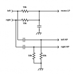
In the pics u ll see the buffer for the L and R with HP and the L+R and then the awfull altogether stuff. Besides adjustmets, it just fails to work altogether when joined:
Here just the LHP:

Here the L+RLP: (incredibly DC is at about -2.5V)

And here the little frankenstein:

Despite both circuits need some adjustment to get the -3dB point coincident, i sort of get what i want, but when i connect both things in parallel to the AC generator the filters go mad. It may be an awfull abomination but this is as far as i got, is there an easy way to isolate both circuits if they share the signal, or my attemps are worthless altogether?
In the pics u ll see the buffer for the L and R with HP and the L+R and then the awfull altogether stuff. Besides adjustmets, it just fails to work altogether when joined:
Here just the LHP:
Here the L+RLP: (incredibly DC is at about -2.5V)
And here the little frankenstein:

The power amps will load the filters somewhat, and may reduce gain and shift frequencies.
Adjusting the R and C values appropriately should be able to work well enough.
For discrete BJT circuits, I've always used the emitter bias type. Wikipedia has a good description:
https://en.wikipedia.org/wiki/Bipolar_transistor_biasing
Adjusting the R and C values appropriately should be able to work well enough.
For discrete BJT circuits, I've always used the emitter bias type. Wikipedia has a good description:
https://en.wikipedia.org/wiki/Bipolar_transistor_biasing
Last edited:
didnt knew wiki was so clear in this topic! thanks again! interesting, we are encouraged to use the emitter bias at the uni, i ll give it a try for sureThe power amps will load the filters somewhat, and may reduce gain and shift frequencies.
Adjusting the R and C values appropriately should be able to work well enough.
For discrete BJT circuits, I've always used the emitter bias type. Wikipedia has a good description:
https://en.wikipedia.org/wiki/Bipolar_transistor_biasing
In class today we saw the emitter bias for AC without the bypass cap on Re --> turns out, now i have two separate current generators with just one transistor, and all is independent from Hfe or other related transistor hybrid parameters. Still have a couple of months to adjust, but it seems promising.

- Home
- Amplifiers
- Solid State
- First project --> BJT adder for subwoofer with embeded crossover