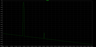
I went back and tried some different tubes in simulation for the FVP. I tried the 6922 and ECC88. The 6922 had 3%THD and the ECC88 had 5%THD. Yes this were driving the input with 1Vrms. When driving them with 100mV things did improve, the 6922 shows .3%. I know not to take the distortion analysis in LTspice as gospel but usually it paints a pretty good picture for what is going on.
Maybe the reason the FVP sounds so good is because of the distortion characteristics, it's not just say 2H, it has high amounts of third, fourth, fifth, etc....I use this technique for guitar amps to obtain a colorfully full sound. I am just thinking it will loose clarity during heavy passages where lots of things are going on, like an orchestra.
I attached an FFT log of the FVP using 6922 tube.
I am not buying those distortion figures. the only source of distortion in this design is from the first triode. model that with the simple load leaving off the cathode follower and it will give a fairly accurate idea of what to expect from the design.
Joes figure of 0.05% with 1vrms output is measured rather than simulated.
Look at the measured spectrum, the real world figure should be better because this includes the phono stage:
http://www.vacuumstate.com/images_upload/gross/fvp_dist_s.gif
Shoog
Last edited:
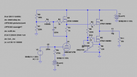
Since we're throwing around schematic suggestions and distortion measures...
Here's what I'd do!
At about 3.6 VPP output simmed Total Harmonic Distortion: 0.024528%. My experience from similar circuits says that in reality it would be less with that output level.
It's ok though, with no feedback applied.
With headphones one can easily hear sub 0.1% distortion differences.
Here's what I'd do!
At about 3.6 VPP output simmed Total Harmonic Distortion: 0.024528%. My experience from similar circuits says that in reality it would be less with that output level.
It's ok though, with no feedback applied.
With headphones one can easily hear sub 0.1% distortion differences.
Attachments
With regard to the FVP and simulations I really recommend reading this thread with an open mind, especially the last few comments where someone describes their actual measured results in comparison to simulations.
http://www.diyaudio.com/forums/tubes-valves/23397-vacuum-state-electronics-fvp5a.html
Its essential that you also consider what they are going to be doing in the real world so applying excessive signals where you force higher order harmonics to dominate isn't really very informative of anything.
Simulations can only tell you if you are on the right track, not the final destination.
Shoog
Last edited:
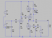
I looked at the datasheet for the 6922 and decided to draw the operating point and loadline (attached) and saw that it looked pretty linear for anything up to a volt or so, I count 4 lines or 20v swing positive and negative for 1 volt change at the grid. So I went back and simulated just a common cathode gain stage at that operating point and the THD indeed was much better. I then went back and looked at the simulation for the FVP and did notice that once I split the two circuits apart the distortion was being created by the follower section😕
I will also attach my schematic for the FVP I am using for the simulation, if anyone could double check it I would appreciate it.
I will also attach my schematic for the FVP I am using for the simulation, if anyone could double check it I would appreciate it.
Attachments

Change C3 to 0.22uf. Simulating at 22uf is going to mess things up and probably force you to use a lower resolution simulation.
Shoog
Shoog
Last edited:
Change C3 to 0.22uf. Simulating at 22uf is going to mess things up and probably force you to use a lower resolution simulation.
Shoog
Hey Shoog, good catch I must have missed the period key when typing. Unfortunately it does not help the simulation. Anyway after reading the links you have posted regarding actual performance and measurements I have no doubt it is a good sounding preamp, the key is the elegant output.....like you said the first stage is just a good old common cathode stage. I have also been doing a lot of digesting Broskie's Aikido and the power supply noise rejection is just the tip of the iceberg, the more I look at it the more I like circuit🙂
I have been looking through more schematics and see that the larger companies like McIntosh use lots of feedback in their preamp designs, but the trend around the diy community seems to be against using feedback. Can anyone give me some reasons to why they chose to not use feedback in their designs? Especially since my tube based power amps use 20db of feedback is there any benefit to not use feedback in my preamp?
Currently the Aikido is in lead, but I have not ruled out the FVP or my own creation. I will need a phono section and the FVP has that in it's design😀 BUT I was thinking of keeping the phono section separate and strictly just do a line stage. What are peoples thoughts on this? Do you prefer a preamp with the phono section already included or is it a good idea to have everything separate? I was toying with the idea of building the phono preamp after I build the linestage............I really want to have the phono pre to have it's own dedicated power supply in it's own separate chassis.
Thanks
-bird
Do a Google search for this article, It's most enlightening.I have been looking through more schematics and see that the larger companies like McIntosh use lots of feedback in their preamp designs, but the trend around the diy community seems to be against using feedback. Can anyone give me some reasons to why they chose to not use feedback in their designs? Especially since my tube based power amps use 20db of feedback is there any benefit to not use feedback in my preamp?
"Negative feedback in audio amplifiers: Why there is no such thing as too much"
Bruno Putzeys -July 24, 2013
As for the FVP5A, the added 1 meg resistors correctly sets the "ultra linear cathode followers" bias points. The bypass cap value can be 0.1uF to 1.0uF.
With the cap overall gain is 18dB without 12dB.
Rick
Attachments
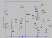
The FVP5 biases up fine without any of those additional items, though the two meg resistor chain will reduce the overall gain if it proves to high.
-------
The question of why many choose to avow gNFB in their preamp designs is a complex one. Ultimately I think its what people decide sounds best to them after listening to the outcome of both approaches. Feedback will make different designs sound almost indistinguishable - so why go to all the extra trouble of building with valves when you could achieve the same result with the ultimate feedback device an opamp ?
I personally think that zero global feedback designs can preserve more detail and that is why I choose to build that way. Its not up to me to persuade anyone that what I have decided is right for them.
Shoog
Exactly. Also there's a limit to the usefulness of low O/P impedance alone.
- Status
- Not open for further replies.
- Home
- Amplifiers
- Tubes / Valves
- First Preamp build