Hey guys🙂
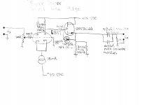
I have built a passive preamp and am happy with the results. My next goal is to build an active preamp. I was thinking of just a buffer using some cathode followers but I think I would like some gain. I am open to any recommendations for cloning a proven design, or kit. I am also tinkering around with some ideas in my own head that I would like to run by you professionals out there. I would like to state that I am by no means an engineer so please be easy on me😱 My giant box of vintage 6SN7's are just begging me to use them in something so I figured a line amp would be cool. I would like to state that I did not look at any schematics using a 6SN7 line amp, I just looked at datasheets and tried to pick some okay looking operating points. I was aiming for a gain of around 14db and I am not a purist so caps and feedback are okay with me. I went with 26db of feedback to get the gain and distortion low enough. Simulation shows low distortion <.002% I will probably be using a B+ of 350V, and most likely regulated, I have some high voltage Maida style regulator boards ready to use.
Any gross mistakes I am missing? Should some compensation be used around the feedback loop to correct any phase shifts?
Thanks for taking the time to look in advance
-bird
Attachments

Hey guys🙂
I have built a passive preamp and am happy with the results. My next goal is to build an active preamp. I was thinking of just a buffer using some cathode followers but I think I would like some gain. I am open to any recommendations for cloning a proven design, or kit. I am also tinkering around with some ideas in my own head that I would like to run by you professionals out there. I would like to state that I am by no means an engineer so please be easy on me😱 My giant box of vintage 6SN7's are just begging me to use them in something so I figured a line amp would be cool. I would like to state that I did not look at any schematics using a 6SN7 line amp, I just looked at datasheets and tried to pick some okay looking operating points. I was aiming for a gain of around 14db and I am not a purist so caps and feedback are okay with me. I went with 26db of feedback to get the gain and distortion low enough. Simulation shows low distortion <.002% I will probably be using a B+ of 350V, and most likely regulated, I have some high voltage Maida style regulator boards ready to use.
Any gross mistakes I am missing? Should some compensation be used around the feedback loop to correct any phase shifts?
Thanks for taking the time to look in advance
-bird
your design looks overly complicated with one more gain stage than is strictly necessary.
I suggest you look at the FVP5 for inspiration;
http://www.tnt-audio.com/gif/fvp5a_schem.gif
just build the second half of the schematic. An excellent performing amp with low distortion without feedback. Should be adaptable to use your 6SN7
Alternatively look at the Aikido, this has fallen out of favour recently but simply because its so tried and test without any novelty, but a solid performer;
12sn7aikido.gif gif by renatod | Photobucket
Shoog
I'll 2nd the aikido advice, if you have a box of tubes to use.
4 tubes for one stereo gain stage.
Otherwise would something like a gyrator or CCS over the first triode to get any gain you want, and then use the second triode as a cathode follower, so one tube per channel?
4 tubes for one stereo gain stage.
Otherwise would something like a gyrator or CCS over the first triode to get any gain you want, and then use the second triode as a cathode follower, so one tube per channel?
So I had some more time to look over all your suggestions.
Hi Eli, Thank you for your schematic, looks like a very nice topology with very low distortion, .03% THD in a simulation. I might like to do away with the Mosfet source follower and use a cathode follower to keep it all tube🙂
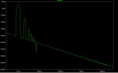
Hi Shoog, That FVP5 looks interesting, but I fail to see how it is less complicated than my schematic😕 It is using four triodes as apposed to my three and has MUCH higher distortion then I would like, see attachment, I think it might color the sound more than I would like. Driven by 1Vrms it is putting out 4.2Vrms @ 1% THD😱 I am not sure if this is because I am using a 6SN7 instead or what.
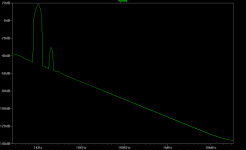
The Aikido looks very nice indeed, and I have heard good things about it. Distortion looks okay, I would like it to be lower @ .3%THD but the FFT shows it's dominated by H2, just a slight bump at 3rd harmonic🙂
The Aikido uses 4 triodes and mine only uses three, and mine yields .0025% THD 😀
Is the fact that I used feedback the reason it is frowned upon? It seems like feedback is a no no around these parts🙁
A pile of 6SN7s, you said.
The uploaded hen "scratch" schematic can be used, with or without, NFB. A differential gain block driven at only 1 I/P can produce no more than 1/2 μ.
Hi Eli, Thank you for your schematic, looks like a very nice topology with very low distortion, .03% THD in a simulation. I might like to do away with the Mosfet source follower and use a cathode follower to keep it all tube🙂
your design looks overly complicated with one more gain stage than is strictly necessary.
I suggest you look at the FVP5 for inspiration;
http://www.tnt-audio.com/gif/fvp5a_schem.gif
just build the second half of the schematic. An excellent performing amp with low distortion without feedback. Should be adaptable to use your 6SN7
Alternatively look at the Aikido, this has fallen out of favour recently but simply because its so tried and test without any novelty, but a solid performer;
12sn7aikido.gif gif by renatod | Photobucket
Shoog
Hi Shoog, That FVP5 looks interesting, but I fail to see how it is less complicated than my schematic😕 It is using four triodes as apposed to my three and has MUCH higher distortion then I would like, see attachment, I think it might color the sound more than I would like. Driven by 1Vrms it is putting out 4.2Vrms @ 1% THD😱 I am not sure if this is because I am using a 6SN7 instead or what.
The Aikido looks very nice indeed, and I have heard good things about it. Distortion looks okay, I would like it to be lower @ .3%THD but the FFT shows it's dominated by H2, just a slight bump at 3rd harmonic🙂
The Aikido uses 4 triodes and mine only uses three, and mine yields .0025% THD 😀
Is the fact that I used feedback the reason it is frowned upon? It seems like feedback is a no no around these parts🙁
Attachments
The Aikido is a good start
An Aikido octal stereo board (Aikido Octal Stereo PCB) would be a good and easy way to get your feet wet. I've built several, kits and point to point wired from scratch. With a little tube rolling the performance (as heard rather than measured) can be quite beguiling. To save a bunch of messing about it's easiest to buy the board, resistor and capacitor packages, tube sockets and stand-offs all from Broskie. If you want to use better tube sockets than the Chinese ceramics try Beltons. I tend not to get hung up on distortion numbers. A no-loop-feedback design with a power supply noise cancelling feature like the Aikido just sounds like music to my ears. So what if it uses 4 tubes? My preference would be to run it at a max B+ of 300 volts.
Cheers, Steve
I have yet had a chance to look at Frank's preamp yet, I still can't find the actual schematic.
I really do like the Aikido and is most likely my first choice for a "clone", although Eli's schematic I keep going back to......I really like it🙂 And I haven't looked at Frank's schematic yet so I don't want to count that out. I just think it would be cool to use something I designed. Also I am using tube power amps similar to the Mullard 5-20, since the majority of the distortion will be made in the power amps, and knowing that I really like the sound with just a passive preamp, I would like the active preamp to be as "transparent" as possible, so I am shooting for something with really low distortion still using tubes.......this leaves me using a lot of feedback and 3 stages. If I were to be using a super clean solid state power amp then well maybe I would be looking for a preamp that added a touch of harmonic color🙂
I really do like the Aikido and is most likely my first choice for a "clone", although Eli's schematic I keep going back to......I really like it🙂 And I haven't looked at Frank's schematic yet so I don't want to count that out. I just think it would be cool to use something I designed. Also I am using tube power amps similar to the Mullard 5-20, since the majority of the distortion will be made in the power amps, and knowing that I really like the sound with just a passive preamp, I would like the active preamp to be as "transparent" as possible, so I am shooting for something with really low distortion still using tubes.......this leaves me using a lot of feedback and 3 stages. If I were to be using a super clean solid state power amp then well maybe I would be looking for a preamp that added a touch of harmonic color🙂
I might like to do away with the Mosfet source follower and use a cathode follower to keep it all tube
When you find a tube with the very high transconductance of the IRFBC20, please let me know. The large transconductance equates to a low O/P impedance and superb drive capability. Zero heater current draw, no concern about heater to cathode potential limits, and incredible ease of setup are other things the FET has in its favor. Sonicly, properly set up FET voltage followers are highly transparent.
JMO, all tube is a fetish. Carefully thought out tube/FET hybrid circuitry frequently does a better job than either device type, alone, is capable of. 😀
I agree that the Mosfet is better in regards to zero heater current, and easier to setup. I am not trying to use all tube because of a "fad" or "fetish"......it's merely a design goal of trying to achieve good performance using tubes.
In regards to the transconductance I read in the datasheet Vds = 50 Id = 1.3A so this would equal 1.3/50=.026 or 26000 micromhos or .026mA/V
I do have some 12HL7 tubes laying around that have a transconductance of 21000 micromhos. Obviously the IRFBC20's 50 watt dissipation beats the 12HL7's 10 watts.
http://www.r-type.org/pdfs/12hl7.pdf
In regards to the transconductance I read in the datasheet Vds = 50 Id = 1.3A so this would equal 1.3/50=.026 or 26000 micromhos or .026mA/V
Peruse the IRFBC20 data sheet again. With VDS = 50 V., ID = 1.3 A., pulse width ≤ 300 μs., and duty cycle ≤ 2 %, the transconductance (gfs) is a staggering 1.4 A./V. In audio service, the transconductance definitely comes down. However, for ID = 20 mA., at least 20 mA./V. is a very real expectation. In the schematic I uploaded, ID is approx. 38 mA. Look for an O/P impedance of about 26 Ω.
Shouldn't 26,000 micromhos equal 26mA/V?
Maybe you meant .026A/V... ?
Yes it's 26mA/V or .026A/V Thanks good catch🙂
Peruse the IRFBC20 data sheet again. With VDS = 50 V., ID = 1.3 A., pulse width ≤ 300 μs., and duty cycle ≤ 2 %, the transconductance (gfs) is a staggering 1.4 A./V. In audio service, the transconductance definitely comes down. However, for ID = 20 mA., at least 20 mA./V. is a very real expectation. In the schematic I uploaded, ID is approx. 38 mA. Look for an O/P impedance of about 26 Ω.
I agree the IRFBC20 will not be bested by any tubes I have especially with the ease of setup. The interconnects are good quality and short, it's also driving a 100k load. The Mosfet wins but a good old fashioned cathode follower should do just fine. Nothing is set in stone of course...........I have no issues with a hybrid......my original goals was to just use hollow state for signal path duties.
So I had some more time to look over all your suggestions.
Hi Eli, Thank you for your schematic, looks like a very nice topology with very low distortion, .03% THD in a simulation. I might like to do away with the Mosfet source follower and use a cathode follower to keep it all tube🙂
Hi Shoog, That FVP5 looks interesting, but I fail to see how it is less complicated than my schematic😕 It is using four triodes as apposed to my three and has MUCH higher distortion then I would like, see attachment, I think it might color the sound more than I would like. Driven by 1Vrms it is putting out 4.2Vrms @ 1% THD😱 I am not sure if this is because I am using a 6SN7 instead or what.
The Aikido looks very nice indeed, and I have heard good things about it. Distortion looks okay, I would like it to be lower @ .3%THD but the FFT shows it's dominated by H2, just a slight bump at 3rd harmonic🙂
The Aikido uses 4 triodes and mine only uses three, and mine yields .0025% THD 😀
Is the fact that I used feedback the reason it is frowned upon? It seems like feedback is a no no around these parts🙁
The FVP is an elegant design and sounds very good, I have built four different versions and they all sound much the same. It has no loop feedback, which is where it is much more appropriate and it doesn't generate gain to then chuck it away. I wouldn't trust your simulation results to much. The second stage was used as an input buffer in oscilloscopes so introduces almost no distortion in of itself. If you want to lower the distortion then slap a CCS or a triode over the input triode which will take you close to the Akido.
Unless you have a particularly insensitive amplifier you are almost never going to be putting 1V into these preamps, its much more realistic to test it at 100mV.
Really the issue here is do you believe that your simulated .0025% design with high levels of loop feedback will be better than these zero loop feedback designs. I suppose its a matter of belief but I would guess that your design will sound fairly flat and sterile and like almost any commercial solid state product you could buy.
Shoog
Last edited:
Joe Rasmussen offers measured distortion figures of 0.05% @ 1V RMS output for the FVP preamplifier, which is a typical high listening level for most people.
Joe's FVP Page
Shoog
Joe's FVP Page
Shoog
Joe Rasmussen offers measured distortion figures of 0.05% @ 1V RMS output for the FVP preamplifier, which is a typical high listening level for most people.
Joe's FVP Page
Shoog
Very few, if any, individuals can hear 0.5% THD and that's with a sine wave. The threshold of noticeability for a complex musical waveform is quite a bit higher.
Once THD does not exceed 0.3%, you definitely are good to go. Lower percentages are advertising copy.
The FVP is an order of magnitude better than that.Very few, if any, individuals can hear 0.5% THD and that's with a sine wave. The threshold of noticeability for a complex musical waveform is quite a bit higher.
Once THD does not exceed 0.3%, you definitely are good to go. Lower percentages are advertising copy.
I don't want to sound overly critical of the original design, I am sure it would sound fine and perform well. I just don't share the design philosophy of creating lots of gain just so you can get the distortion figures vanishingly low by reducing the gain back down to manageable levels. I really do feel something is lost in that process, but thats my philosophical belief rather than a hard empirical one.
Shoog
I hear the argument that humans can't hear .5% THD..........but this isn't a power amp, it's a preamp which means all that added distortion made by the preamp will get multiplied going through the power amp. I am also sure that once I stick a volume pot in front it will probably be only seeing 100mV - 500mV from the line stages, I just like to test THD at full output for worst case scenario situations.
I will go back and take another look at the FVP, like I said I was testing it with 6SN7's which is not what the schematic calls for.
I hear the argument against no feedback all the time, I just fail to see any hard evidence that it is bad, maybe if there is a transformer in the loop, but there isn't. In regards to the comment about my design possibly sounding sterile or flat, that was kind of what I was going for. I definitely don't want to get too hung up on distortion figures, but I also don't want an effects box.
When I get more time I will revisit the FVP and try and find Frank's schematic.
Thanks again guys for all the input🙂
I went back and tried some different tubes in simulation for the FVP. I tried the 6922 and ECC88. The 6922 had 3%THD and the ECC88 had 5%THD. Yes this were driving the input with 1Vrms. When driving them with 100mV things did improve, the 6922 shows .3%. I know not to take the distortion analysis in LTspice as gospel but usually it paints a pretty good picture for what is going on.
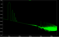
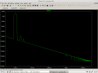
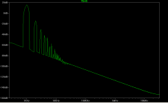
Maybe the reason the FVP sounds so good is because of the distortion characteristics, it's not just say 2H, it has high amounts of third, fourth, fifth, etc....I use this technique for guitar amps to obtain a colorfully full sound. I am just thinking it will loose clarity during heavy passages where lots of things are going on, like an orchestra.
I attached an FFT log of the FVP using 6922 tube.
Attachments
- Status
- Not open for further replies.
- Home
- Amplifiers
- Tubes / Valves
- First Preamp build