Hi Guys,
I decided to try and design some PCBs to suit Carlos' Snubberised LM338 PSU.
LM338 regulated snubberized PSU for audio amplifiers


Does anybody see anything obviously wrong here?
Here is the schematic

I've designed the PCB to use off board rectifiers and spade connections for I/O.
I decided to try and design some PCBs to suit Carlos' Snubberised LM338 PSU.
LM338 regulated snubberized PSU for audio amplifiers
Does anybody see anything obviously wrong here?
Here is the schematic
I've designed the PCB to use off board rectifiers and spade connections for I/O.
Last edited:
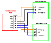
When laying out bipolar power supply PCBs with connectors for two amp channels,
I often put the regulated-positive-output terminals next to each other. In your layout, "+Ve A" adjacent to "+Ve B". Perhaps even adjacent terminals within a single high current Euroblox terminal block.
Similarly, I often put the negative-output terminals next to each other: "-Ve B" adjacent to "-Ve B".
In my experience, this reduces the number of PCB cross-unders and vias on high current paths.
_
Attachments
Hi guys, thanks for the advice. Here's my version 2.0
I tried to make use of as much copper area as possible. I figure it will aid in current handling and heat dissipation as well as reduce cost.
I both increased the size of the vias and the number.
I moved the outputs around as suggested; both +ve outputs beside each other etc. It doesn't suit my aesthetic sensibilities but it did drastically simplify the tracing.
Well folks,
I made a few minor changes but as above is basically what I've come up with.
I had some issues with nets that I couldn't quite figure out. Easyeda threw up some net errors however I chose to ignore these as I am certain everything is in the right place.
EasyEDA also threw up some layout errors but once again I chose to ignore them as I'm certain everything is in the right place.
I've submitted the order to JLCpcb. It cost me a little more than like $60 for 10 pcbs with double weight traces, blue colour and DHL shipping. Surprisingly cheap and easy for a nub.
I'll see what arrives in a few weeks.
Last edited:
Another technique I have used with ground or power planes over the years is pouring the plane in a crosshatch. Creats more surface area.
The board looks pretty good!
'Snubberized' I like that
Thanks,
I cannot take any credit for the circuit. That belongs to Carlos Filipe.
My only concern with the board is that I haven't left enough room between the traces. At it's smallest there is only 0.6mm between the traces. Does anybody know what the insulation resistance of pcb silkscreen is?
Production is almost finished on the PCBs so if I am lucky and DHL are feeling really generous, I might see the boards arrive by next Friday.
First up to use them is a project 3A from Rod Elliot at ESP. 5A per rail should be plenty for 50W per channel.
Last edited:
Another technique I have used with ground or power planes over the years is pouring the plane in a crosshatch. Creats more surface area.
The best power planes are all copper.
More copper to soak up interference and screen.
Leaving more copper on the pcb reduces chemicals used to remove copper.
Also, the Gerber spec doesn't recommend cross hatches as it generates huge Gerber files.
Crosshatch does little except remove useful copper. When you have a layout that is so close to 100% copper like that, there's no warping problem either, and that was a reason why some folks used the crosshatching on large pours.
Close to 100% copper is fantastic, especially for multilayer stackups. Skip the crosshatch and be happy!
Close to 100% copper is fantastic, especially for multilayer stackups. Skip the crosshatch and be happy!
Logistics Porn
Hey guys,
Here is some logistics pornography.

I am amazed at how quickly Zee Germans can get stuff moving.
Our local couriers in Auckland New Zealand cannot reliably get stuff from one side of Auckland to the other in 1 day let alone out of the country.
DHL for the win.
Hey guys,
Here is some logistics pornography.
I am amazed at how quickly Zee Germans can get stuff moving.
Our local couriers in Auckland New Zealand cannot reliably get stuff from one side of Auckland to the other in 1 day let alone out of the country.
DHL for the win.
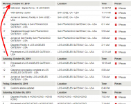
I'm using DHL to ship boards too. Notice how they sat in Los Angeles, motionless, for 50 hours. From Saturday morning to Monday morning. Argh!!
_
For shipments to the UK the longest part seems to be waiting for DHL to pick up the item in the first place.
I find UK customs strange, it seems to be random as to whether or not I pay customs charges. I think the breakpoint is about £15 before customs charges are paid. My last two orders were £30 yet no charges.
I did get caught out a while back when an item was checked by customs and I didn't realise they needed a invoice to check the item cost.
What shouldnt have had a customs charge ended up wit ha customs charge and a holding fee.
Despite the Hong Kong protests so far I haven't noticed any delays in shipments.
- Status
- This old topic is closed. If you want to reopen this topic, contact a moderator using the "Report Post" button.
- Home
- Amplifiers
- Power Supplies
- First PCB Fab Attempt