Hello all,
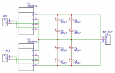
I have decided to try and design my first PCB, so I thought I'd start with something simple; rectification plus caps. This is planned for a phono preamp. Any suggestions for improvements?
Thanks in advance
I have decided to try and design my first PCB, so I thought I'd start with something simple; rectification plus caps. This is planned for a phono preamp. Any suggestions for improvements?
Thanks in advance
Attachments

Last edited:
why do you use the filter caps in series? this will halve their capacity value (but double voltage rating, maybe that's the reason).
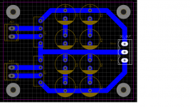
you could also make the traces even thicker or use polygon shapes instead. if you etch the PCB at home this will save etching acid! or you make ground copper fills.
and while saving: you could save some PCB space if you rearrange the components a bit tighter, but that's just personal preference.
edit: one more idea could be to include resistors between the cap blocks. you can short them with wire bridges for now and have the possibility to insert resistors for a CRC filter, if needed later on.
Last edited:
Why are you etching away so much copper? I did a bank recently. Basically just cut three slices down a bit of board.
Make enough space for the output leads for the power and ground "star" point. Phono amp, you need to really pay attention to performance. Are you following it with a regulator? Single or cascaded? I have seen where you use something crude like 317's as a pre-regulator on the cap board, then higher performance closer to the amplifier.
Where are your fuses? Any snubber?
Phono preamp requires low noise at the expense of esentally any other parameter. I‘d suggest including a series resistor in stern cap banks to make a CRC filter.
I agree with the other commenters on you’ve removed too much copper as well as there is no reason to have the capacitors stacked in series.
You also may want to consider adding a input snubber for the rectifiers.
I agree with the other commenters on you’ve removed too much copper as well as there is no reason to have the capacitors stacked in series.
You also may want to consider adding a input snubber for the rectifiers.
Thanks for the replies.
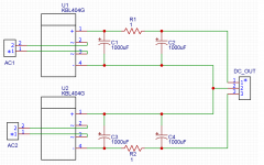
I completely agree with the capacitors in series. I will change those so that all are in parallel.
@stv - Thanks for the input. I was planning on having some of these made at JLPCB or Oshpark.
@tvrgeek - This will be plugged straight into the RJM VSPS, so the regulators are just LM7812/LM7912. The fuse is built into the power input. I did not consider snubbers for the rectifiers. I'll look into that.
@6L6 - A CRC filter would be a better idea. I'm guessing that 1ohm would be good.
Take each ground of each input capacitor directly back to its own rectifier.
Do not connect the two rectifiers together directly.
Only connect the two circuits together at the output terminal.
Do not connect the two rectifiers together directly.
Only connect the two circuits together at the output terminal.
CRC can be amazing. How much you can model in Spice. On my power amp, I use 22 Ohms between the main bank and the 220uF feeding the IPS and VAS. But I am starting with a 56 V supply and I clip my VAS only about 2V below the outputs clipping. If you have not bought your transformer yet, you have the opportunity to throw away voltage.
For a board as simple as this, you can just separate areas with a Dremel and save the cost of having one made.
On your VSPS, look at parts carefully to optimize it. There are better regulators and far better op amps. Be sure you select the cartridge loading resistors to match your cartridge. ( R1, 47K is a "standard" but often not correct). I would consider a film cap for the output coupling. Don't know why R5 is so large. 100 Ohms would work fine and be quieter.
That output terminal should be the circuit star ground.Take each ground of each input capacitor directly back to its own rectifier.
Do not connect the two rectifiers together directly.
Only connect the two circuits together at the output terminal.
Personally, I would use just a CT transformer and a single bridge. I am not convinced even for a phono board if independent are any benefit. Not at the level of a single stage op-amp board. I would cascade regulators first. Everyone has their preferences of course.
@rayma - Will do! Thank you
@tvrgeek - I haven't done any SPICE modeling since university. Maybe it's time to brush off my skills. I'll take a look at PSUD2 as well. Since I'm using the pcb from RJM I'm kind of stuck with the 3-pin regulator. What would you recommend as being better than lm7X12? Would a pre-regulator on my PCB be just as good?
For the output caps I am already using Mundorf MKPs. For loading I am using RJMs switchboard PCB to switch in 10k and 8k for resistive loading and 4 100uF caps for 100 to 400uF of capacitive loading.
VSPS shows R5 as 47r. Are you thinking of a different resistor for changing to 100r?
Thanks!
Hello knauf1919 - Thank you for the reply. EasyEda is what I have been using. I don't have much experience but am muddling my way through pretty well. If I get to something that I can't figure out I may pm you.
You can put the .json file here and we are working on it.
For now, give it a try and see what comes out. Even if it is wrong, it is not the problem, everything has a beginning.
For now, give it a try and see what comes out. Even if it is wrong, it is not the problem, everything has a beginning.
I miss read it. Yes it shows 47 Ohms. That is fine. I think you mean "pF" not "uF" on loading. 🙂
As the old regulators were noisier than the new, not sure pre-reg would do much better. You can get 3 pin modules using newer lower noise regulators that will the form factor of a 3 terminal. Something based on the TPS7A30 series. I would pay the most attention to the star ground. I would also put the amp at the base of the arm with the supply remote.
I think I would do the cartridge loading directly on the amp. Just my preference.
OK, time for a second go at this. I decided to forgo the snubbers for now since I need to read more about them; maybe I'll add them later after I understand more. The caps farads were doubled and a 1r resistor added in between for a CRC.
@tvrgeek - Yes, pF not uF. Brain fart......
Thanks everyone for the input. If you have more I'm more that happy to listen and learn.
@tvrgeek - Yes, pF not uF. Brain fart......
Thanks everyone for the input. If you have more I'm more that happy to listen and learn.
Attachments
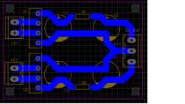
Make sure that the blue traces are on the bottom side of the board, and not on the top side
where the capacitors are mounted. There are exposed metal contacts on the bottom
of the capacitors, that can short to traces placed on the top side of the board, which could
short out the capacitor.
where the capacitors are mounted. There are exposed metal contacts on the bottom
of the capacitors, that can short to traces placed on the top side of the board, which could
short out the capacitor.
Blue = bottom
Red= top
... in Easyeda by default. 🙂
Make the diagram first. After that you choose the components you use. Farnell Mouser TME DigiKey, etc. they are your friends.
Red= top
... in Easyeda by default. 🙂
Make the diagram first. After that you choose the components you use. Farnell Mouser TME DigiKey, etc. they are your friends.
Last edited:
- Home
- Amplifiers
- Power Supplies
- First PCB design, looking for feedback