Hello,
I will be building an Active filter for my mini subwoofer and sattelites. I have found a circuit I would like to use here:
Subwoofer Filter Circuit
Questions:
1. Since this is an audio circuit, any recommendations on OPAMP selection? Sound quality is important.
2. I assume since each L/R channel contains 1 full OPAMP IC plus half another OPAMP that it's not a good idea to mix the half IC across each channel L/R, but rather use only 1/2 of an IC for each channel, correct?
3. Any other recommendation on component type/quality?
4. For PCB design, recommendations on design software? It would be nice to design and order the PCB online from one source. But if not, any suggestions on where I can have the PCB manufactured?
5. I assume this circuit must have a - / 0 / + power supply, correct?
Feel free to add any other suggestions. Thanks in advance for all your assistance on my first PCB and audio project!
I use Sprint Layout (Abacom)
It doesn't cost a fortune (around $50), easy to work with and produces Gerber and Excelon files, needed by the pcb factory.
Usualy I do my pcbs at home.
I only order once from Sky Electronic Mart.
Not very expensive and I was able to get only 2 boards. Usualy they ask for a minimum of 5 or 10 boards
The schematic shows 10 opamps.
If you use duals you will need 5 duals.
If your use quads you will need 3 quads.
If you use singles you will need 10 singles.
Most filter circuits require jFET input opamps.
That removes the 833, 5332 & 5334 from your suitable opamps list.
All the inputs and all the outputs are AC coupled.
You thus have the option to use either single polarity supply (and change the schematic to suit), or use a dual polarity supply and use the schematic as shown.
I'd suggest the filtering resistor values be kept in the range 4k7 to 15k. Adjust the capacitor values to fit with that and then select a value that is in the E6 range (and hand match to ~1% by buying a few extra 5%, or 10%, film capacitors) and fine tune by using multiple resistors of 1% tolerance
Last edited:
Opamp filter advice
Hi Andrew,
Thanks for giving me detailed suggestions.
Perfect! I had planned on using duals. I thought there might be possible crosstalk by splitting the duals across two channels. If it's not a concern I can split the one dual across the L/R channels.
I think I'll stick with the original schematic for now. Thank you for the suggestion.
I think the schematic is setup to filter at 200HZ for both the HP and LP sections. Is that not correct? I wouldn't know how to adjust the resistors and capacitors to meet those target filter frequencies. Is there an advantage to manually adjusting the values? Perhaps it is difficult to get high tolerance caps at the values listed in the schematic. Let me know.
Hi Andrew,
Thanks for giving me detailed suggestions.
The schematic shows 10 opamps.
If you use duals you will need 5 duals.
Perfect! I had planned on using duals. I thought there might be possible crosstalk by splitting the duals across two channels. If it's not a concern I can split the one dual across the L/R channels.
You thus have the option to use either single polarity supply (and change the schematic to suit), or use a dual polarity supply and use the schematic as shown.
I think I'll stick with the original schematic for now. Thank you for the suggestion.
I'd suggest the filtering resistor values be kept in the range 4k7 to 15k. Adjust the capacitor values to fit with that and then select a value that is in the E6 range (and hand match to ~1% by buying a few extra 5%, or 10%, film capacitors) and fine tune by using multiple resistors of 1% tolerance
I think the schematic is setup to filter at 200HZ for both the HP and LP sections. Is that not correct? I wouldn't know how to adjust the resistors and capacitors to meet those target filter frequencies. Is there an advantage to manually adjusting the values? Perhaps it is difficult to get high tolerance caps at the values listed in the schematic. Let me know.
PCB Design Website Advice
Thank you jpr_pt. I will check out Sprint Layout. I also found EasyEDA in another post which looks interesting: EasyEDA - Web-Based EDA, schematic capture, spice circuit simulation and PCB layout Online
I use Sprint Layout (Abacom)
It doesn't cost a fortune (around $50), easy to work with and produces Gerber and Excelon files, needed by the pcb factory.
Usualy I do my pcbs at home.
I only order once from Sky Electronic Mart.
Not very expensive and I was able to get only 2 boards. Usualy they ask for a minimum of 5 or 10 boards
Thank you jpr_pt. I will check out Sprint Layout. I also found EasyEDA in another post which looks interesting: EasyEDA - Web-Based EDA, schematic capture, spice circuit simulation and PCB layout Online
don't try to buy capacitors with E96 values and <1% tolerance.
Use cheap metal film resistors to trim to the frequencies you want/need.
Buy polypropylene, polystyrene, or NP0 ceramic and hand match @ near the E6 values that are commonly available.
if the sch says 0.01uF then buy +-5% or +-10% 10nF caps and measure them.
Select pairs, or sets, that match to ~1% (that's equivalent to +-0.5%).
It does not matter that they are actually 10.59nF & 10.48nF. (your cap meter could be +-10%, that does not matter either). What matters is that they are near enough the same as each other.
Download Ti filter pro and play about with some numbers. Ti's older filter software was MUCH better in that you could simulate different values and see the effective Q and Fr and see the response shape. The newer releases removed this flexibility. There are probably others that let you set the component values to see the effect. Your sch has some unusual mixture of values and I cannot by looking see what they are achieving.
Looking at your sch.
it shows 82k, 100k, 120k and 220k filtering resistors.
I don't know why the circuit NEEDS this high resistance.
But, for noise I would reduce them by a factor of 10, to 8k2, 10k, 12k and 22k
To maintain the same frequency you NEED to multiply the associated capacitors by 10 from 0.01uF to 100nF
Last edited:
Looking at your sch.
it shows 82k, 100k, 120k and 220k filtering resistors.
I don't know why the circuit NEEDS this high resistance.
But, for noise I would reduce them by a factor of 10, to 8k2, 10k, 12k and 22k
To maintain the same frequency you NEED to multiply the associated capacitors by 10 from 0.01uF to 100nF
Now I understand the need to adjust the resistors and caps. It sounds like the Ti program (or something similar) will make that easy.
One last question. It looks like P1 is a simple subwoofer output control (not a frequency adjustment). Let me know if I got that right.
Thanks again for your advice!
Attachments
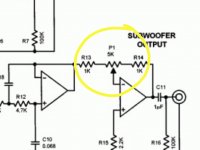
Yes, it allows one to adjust the Bass channel to match the sensitivity of the other channel/s
But it is in the -IN input.
An open circuit here changes the gain.
Even a very short term jump over a bit of dust is enough to create a pulse on the output.
If you can, try to change to an adjust on the input to the +IN pin.
The reason for doing it as shown is to correct the phase reversal of the summing circuit inside the R8 loop.
If the bass does need that extra phase correction, you can apply it at the speaker leads.
- Status
- Not open for further replies.
- Home
- Design & Build
- Construction Tips
- First PCB: 2.1 Active Filter OPAMP and Design Advice