😀😀😀😀
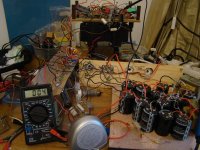
First OTL amp (circlotron concept) breadboarded and sweet music coming out albeit only with 2 x 6080's on 1 channel.
Driver topology a little different to most.
But with only 1-4mV DC.
You can see the voltmeter on the 2000m setting.
Still trying out different designs of CCS on the LTP but so far so good.
Now it's time to build up the tube bank of 6080's and buy some bigger transformers.
Also would like to incorporate some kind of speaker protection.
Maybe relays?
One question about the DC offset.
If I keep the grid bias below -29 volts the dc if low (1-10mV).
If I begin the increase the grid bias to then the dc on the output increases!
I thought the DC balance was due to the balance of the signals from the splitter/LTP.
Also without a 8 ohm dummy load the DC offset is higher. (100mV or more). When I switch on the dummy load or speaker if falls.
Hello Brit01,
It does look sort of fun, However I would stand outside the door when you turn that thing on. There is a certain fear factor. DC offset make me think transformer.
Keep on truckin brother.
DT
It does look sort of fun, However I would stand outside the door when you turn that thing on. There is a certain fear factor. DC offset make me think transformer.
Keep on truckin brother.
DT
pic:
Hello Brit 01
Cool electronic `Jungle`🙂on Your experiment breadboard,hey but Your Circlotron Amp WORK! from first `hit` and thats good 😀
Not sure what kind the driver stage You use there,Tube or SS, but usually DC offset drift come from this driver stage
Keep continue your work,but take care beacose chance to made mistake or circuit short is bigger in that `Jungle`
All the best Man

The DC offset wonders a little but only in the 2-15mV range which is no problem. (my SS has 12-15mV)
Whenever I tried setting the grid bias on each rail equally this is when I got more DC offset.
I could reduce the DC to zero but with each grid bias set to within about 5 volts of each other (in any range, low or high).
I check out and saw that one of the floating supplies voltage is slightly different to the other (maybe explaining the grid bias differences).
I have a small pentode sink on the LTP. I will fiddle with this and also try a SS sink (but had problems finding any negative voltage regulators here. They only have low voltage ones).
Could I use a sink comprised of transistors, maybe DN2540, or 3904's on the LTP?
I've only had experience of cascode DN2540 as sources on anodes but never sinks.
Could a cascode DN2540 be used as a sink to ground on the cathode?
Could a cascode DN2540 be used as a sink to ground on the cathode?
Only if you want superb balance and overall performance with a simple, inexpensive circuit. 😀
Only if you want superb balance and overall performance with a simple, inexpensive circuit.
How would this be implemented as the tail resistor sink in an LTP?
I've only used them as plate sources.
I will try something like this using DN2540 as a sink:
http://www.triodeguy.com/Triodeguy%20PDF%20files/6AS7%20CURRENT%20BALANCED%20PP%20AMP%20SCH.pdf
http://www.triodeguy.com/Triodeguy%20PDF%20files/6AS7%20CURRENT%20BALANCED%20PP%20AMP%20SCH.pdf
DN32540 implemented! Works fine. DC hovers between 0-20mV, back and forth a little.
I have fets as source followers, I have a difference in current through these with 5K on the source.
Is it possible to use Current sinks on a mosfet as source follower?
Instead of a neg. voltage through a resistor on the source output, could I use a cascode DN2540 to ground on the FET?
I have fets as source followers, I have a difference in current through these with 5K on the source.
Is it possible to use Current sinks on a mosfet as source follower?
Instead of a neg. voltage through a resistor on the source output, could I use a cascode DN2540 to ground on the FET?
Last edited:
Working on this more I can achieve 0 volts DC offset if I adjust the grid bias prior to the source folowers correctly.
BUT when they are balanced (zero volts DC), the grid bias voltages are about 8 volts different (-41 and -49 volts for example).
What could this be due to?
1) floating supplies not equal ( about 9 volts difference between the 2 floating power supply transformers)
2) difference is current through the FET source followers
3) difference in tubes
Thinking about this further I suspect the grid bias difference is due to the floating power supply voltage difference.
I assume they must be of equal voltage. Maybe I can reduce the stronger one with a resistor of the correct value and go from there.
It's all a prototype at the moment. Final design will have new trannies.
Well playing with the bias i can achieve zero DC offset and adjust the current through the output tubes (6080) quite easily with the trimmers.
I'll probably incorporate these as control knobs on the chassis.
Got to start thinking about speaker protection now.
A relay maybe that only opens when DC is less than 100mV?
Not sure how to do this yet.
Working on this more I can achieve 0 volts DC offset if I adjust the grid bias prior to the source folowers correctly.
BUT when they are balanced (zero volts DC), the grid bias voltages are about 8 volts different (-41 and -49 volts for example).
What could this be due to?
1) floating supplies not equal ( about 9 volts difference between the 2 floating power supply transformers)
2) difference is current through the FET source followers
3) difference in tubes
Easy to find out.. switch tubes and measure, switch power supplys and measure again,...
Cool, I want to build a circlotron too.
With low mu tubes like this a difference in plate voltage will make a relatively large difference in the cathode, just like u observe. These tubes are not well matched either so that adds up, dynamically that doesn't seem to make much of a deal). Perhaps a slight difference in the cathode followers driving the output adds a little offset as well. The most important is that u can adjust the offset, and that it doesn't drift too far.
With low mu tubes like this a difference in plate voltage will make a relatively large difference in the cathode, just like u observe. These tubes are not well matched either so that adds up, dynamically that doesn't seem to make much of a deal). Perhaps a slight difference in the cathode followers driving the output adds a little offset as well. The most important is that u can adjust the offset, and that it doesn't drift too far.
The most important is that u can adjust the offset, and that it doesn't drift too far.
Yes it is easy to adjust the offset by turning the individual grid bias trimmers before the source follower drivers.
I want to implement Current sinks on the FETs also, instead of a resistor as I'm not getting good matching. I have about -60 volts (a bit low) on the Source, and a 5K resistor but they don't match very well.
Looking at speaker relays now so the speakers are not engaged until the DC offset is below 50-100mV.
Any suggestions for speaker relay protections? Something simple but will engage at around 50mV DC?
😕😕
I swapped power supplies - no change
tube - no change
I will try more tube swapping, maybe I've got a very uneven tube in the batch.
Or could the source followers be causing such a difference in grid bias to get zero DC at the output?
We're looking at 12-14 volts difference between the rails in order to get zero DC.
Nope, tube swapping still the same.
Also I have 100 volts on the plates and around -40 bias. I measure across the cathode resistor, 0.55 volts, 3.9R = 141mA!!!!! (too high)
But the data sheets show more like 60 mA at 100volts, -40 volts grid bias.!!
I'm assuming now it's the current flowing through the FET's. They are not equal, even with the same resistor and neg/pos voltage on drain and source.
I think I will need to tweak the resistor to source or try a current sink regulator such as a 10M45 to match the FETs.
Last edited:
Can we see a complete schematic to your amp? Been thinking of trying a circlotron circuit. BTW, I would definitely implement the CCS for the tail, and try to get your power supply voltages equal. 6AS7 can be a little hard to find a good match, so anything you can do to get them seeing the same voltages won't hurt.
Sorry still working on the design.
I'm thinking if you have 2 floating power supplies in a circlotron, do the voltages actually need to be equal?
Are they not balanced between the 2?
Also varying the current through the FETs had a big effect on the grid bias settting.
I'm thinking if you have 2 floating power supplies in a circlotron, do the voltages actually need to be equal?
Are they not balanced between the 2?
Also varying the current through the FETs had a big effect on the grid bias settting.
- Status
- Not open for further replies.
- Home
- Amplifiers
- Tubes / Valves
- First OTL breadboarded