Wire L1 and L2 so they are across the bulb.
Take L2 on the first switch to L1 on the second switch, and L2 on the second switch should connect to the wire coming off of the bulb.
Take the neutral wire from N2 on the first switch to N1 on the second switch. This way the neutral is only connected to the neon in the second switch (it will be across L2 and N2) when the switch is on.
Test it all with a multimeter before plugging in. There should be no shorts across live and neutral with the switches in any combination!
Is it a good idea to use something, without knowing its purpose?PJPro said:I've no idea.
The switch is there for convenience. Without the switch you would have to plug and unplug the cable. One switch is enough to interrupt a circuit. Even a single pole is sufficient for that and it does not even matter, where in the circuit it is wired in. Double pole is used for safety, to make sure that no voltage is present after the switch, no matter at which polarity it is connected to the mains. Safety is also the reason, why you should wire it according to your schematic in post #58. The live circuit remains as far away as possible from the device under test, when the switch is off.
The version according to Decibel Dungeon is safe in the UK, if you respect polarities. In many parts of the world the mains connectors can be turned by 180° and you never know, which side is the Phase and which is Neutral. So the blue wire could be connected to the Phase and there would be live voltage going through the blue wire to the transformer of the device under test, pass through it and be present at the brown wire's connection to the bulb on the right. The same thing would happen, if you used it in the UK and swapped the wires in the mains connector.
In Decibel Dungeon's schematic the second switch is used to short out the lamp. Once the light bulb tester has shown the device under test to work fine, you don't want to unplug, disconnect the light bulb tester, connect a cable without tester and plug it in. Just flip the switch, short out the bulb and the device is directly connected to mains. To achieve that, connect L1 of the second switch to one side of the lamp and L2 to the other side of the lamp. Connect N2 of the first switch to N1 of the second switch. That will give you an indication of that switch's state as well.PJPro said:The image on decibel dungeon shows a switch simply connected across the bulb.
Hi,
one switch is a master OFF/ON. This is optional.
One switch is bulb bypass. This is optional.
All that is needed is a plug top, a socket outlet, a bulb holder, and an insulating box to make the assembly safe from prying fingers.
The Live line has the bulb holder in it.
The Earth and the Neutral pass straight through from Plug top to Socket outlet.
Ordinarily, I'd say no. Unfortunately, the writeup at decimal dungeon says don't worry about how it works and secondly I've searched on this forum and all I can find is references to some elusive previous post (which explains the workings) that I am unable to find.pacificblue said:
Is it a good idea to use something, without knowing its purpose?
Thanks for the explanations. I'm sure others will find this of value.pacificblue said:
The switch is there for convenience. Without the switch you would have to plug and unplug the cable. One switch is enough to interrupt a circuit. Even a single pole is sufficient for that and it does not even matter, where in the circuit it is wired in. Double pole is used for safety, to make sure that no voltage is present after the switch, no matter at which polarity it is connected to the mains. Safety is also the reason, why you should wire it according to your schematic in post #58. The live circuit remains as far away as possible from the device under test, when the switch is off.
The version according to Decibel Dungeon is safe in the UK, if you respect polarities. In many parts of the world the mains connectors can be turned by 180° and you never know, which side is the Phase and which is Neutral. So the blue wire could be connected to the Phase and there would be live voltage going through the blue wire to the transformer of the device under test, pass through it and be present at the brown wire's connection to the bulb on the right. The same thing would happen, if you used it in the UK and swapped the wires in the mains connector.
In Decibel Dungeon's schematic the second switch is used to short out the lamp. Once the light bulb tester has shown the device under test to work fine, you don't want to unplug, disconnect the light bulb tester, connect a cable without tester and plug it in. Just flip the switch, short out the bulb and the device is directly connected to mains.
If this tool is really as invaluable as some suggest, I am surprised there isn't a lengthy post which goes through how to make the tool and an explanation of how to build it in it's many forms (I understand that decibel dungeon's is considered the deluxe version). Surely, this post would merit sticky status, considering the number of posts I have read requesting information on how the thing works. It would save everyone a lot of time.
OK. Understood. I have updated my diagram to reflect your comments. Does it look OK?pacificblue said:
To achieve that, connect L1 of the second switch to one side of the lamp and L2 to the other side of the lamp. Connect N2 of the first switch to N1 of the second switch. That will give you an indication of that switch's state as well.
Thanks again for your help.

Howdy PJ,
I suggest just forget the switches. I rely on the wall switch or the switch on the equipment under test.
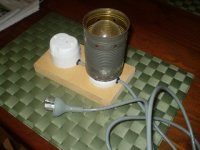
I've attached a pic of my tester. You can see the Aussie spec outlet on the board. I just used a standard mains cable from some appliance or other. Under the bulb is a standard bayonet bulb holder from a ceiling fitting. The shade is a tin can.
Just think of the bulb filament as a continuation of the live wire; in through one terminal on the bulb and out the other. The other two are connected normally to the outlet socket on the left and just pass through under the bulb holder. I just use a 40w bulb for most testing.
Cheers
Stuey
I suggest just forget the switches. I rely on the wall switch or the switch on the equipment under test.
I've attached a pic of my tester. You can see the Aussie spec outlet on the board. I just used a standard mains cable from some appliance or other. Under the bulb is a standard bayonet bulb holder from a ceiling fitting. The shade is a tin can.
Just think of the bulb filament as a continuation of the live wire; in through one terminal on the bulb and out the other. The other two are connected normally to the outlet socket on the left and just pass through under the bulb holder. I just use a 40w bulb for most testing.
Cheers
Stuey
Attachments
Well, it does not take a lenghty explanation, and it has been explained several times without ever getting sticky.PJPro said:I am surprised there isn't a lengthy post which goes through how to make the tool and an explanation of how to build it in it's many forms (I understand that decibel dungeon's is considered the deluxe version). Surely, this post would merit sticky status,
Light bulbs are temperature-dependant resistors. The higher the temperature, the higher the resistance (PTC - positive temperature coefficient). That is, why they usually blow the moment, they are switched on. Their resistance is low then.
Now connect an amplifier in series and switch it on. The inrush current is high and will probably make the bulb light up for a short moment. If the amplifier is okay, there will not be much current draw after that -> low current through the lamp -> no heat, no light -> low resistance -> no voltage drop across the lamp -> full voltage at the amplifier. If the amplifier has a fault, it will draw a big current -> filament heats up, lights up -> resistance goes high -> high voltage drop across the lamp -> reduced voltage at the amplifier. There is your cheap and easy current limiter.
Yes.PJPro said:Does it look OK?
What is wrong with making your life easier, when it only costs two switches? Not everybody has a wall switch for the outlet next to his workplace. E. g. here in Germany outlets usually don't have dedicated switches.Stuey said:I suggest just forget the switches. I rely on the wall switch or the switch on the equipment under test.
And the switch to short the lamp is really practical in the testing phase.
When the builder has not got a clue on what he proposes to build then I would suggest he/she builds the simplest version first.pacificblue said:What is wrong with making your life easier, when it only costs two switches? Not everybody has a wall switch for the outlet next to his workplace. E. g. here in Germany outlets usually don't have dedicated switches.
And the switch to short the lamp is really practical in the testing phase.
Much less likely to make a mistake with the mains wiring could save lives.
Like I say, there would be some value in a thread which ensured the builder understood what the tool was trying to achieve and how to build it.AndrewT said:When the builder has not got a clue on what he proposes to build then I would suggest he/she builds the simplest version first.
Much less likely to make a mistake with the mains wiring could save lives.
I will be documenting the build of this tool over on my diy dual mono power amps thread (on another site). I will include the explanations provided here. I'd ask forum members on this site to review what I've documented and, once it's correct, I'll create a thread on this site. This gets around the limitations placed on editing posts on this site.
The moderator can decide whether or not this new thread is worthy of sticky status. Just the fact that the title of the thread will be Bulb Tester (or something similar) will make it easier for people to find......and when questions are asked in the future, it'll be easy to point people at the right thread.
Alternatively, someone else can create the thread. I don't mind one way or another.
If, however, people think this thread is unnecessary I won't bother with transferring the data from my thread on the other site.
Any thoughts?
pacificblue said:
What is wrong with making your life easier, when it only costs two switches?
Nothing.
OK. Fair enough. Given the lack of any responses, I'll assume that it only me who had problems finding the relevant information....so I won't bother producing a thread for this site.
Thanks for your comments Stuey.Stuey said:Howdy PJ,
I suggest just forget the switches. I rely on the wall switch or the switch on the equipment under test.
I've attached a pic of my tester. You can see the Aussie spec outlet on the board. I just used a standard mains cable from some appliance or other. Under the bulb is a standard bayonet bulb holder from a ceiling fitting. The shade is a tin can.
Just think of the bulb filament as a continuation of the live wire; in through one terminal on the bulb and out the other. The other two are connected normally to the outlet socket on the left and just pass through under the bulb holder. I just use a 40w bulb for most testing.
Cheers
Stuey
Hi PJPro
My suggestion would be to use a suitable momentary foot switch, safely boxed and earthed up, with your bulb on the bench.
You can then be looking at the bulb and circuit when power is applied, and have both hands free to waft the smoke or beat out the flames in my case.
It's quicker to kill the power if there is a fault too if all you have to do is lift your foot.
John
I was thinking (naively), feel free to shout.
The purpose of the carefully chosen, one, two or a few more output stage transistors is to modulate a DC line according to what signal voltage/current they receive at their base. Those transistors have to sweep from virtually shut, to fully open, and that swing involves collector currents from nothing to many amps.
There are very few if any transistors that can pretend to be anything like linear over those amp ranges, and then you get leakages, hfe changes as they get hot and so on. So you may spend ages trying to design a robust output stage, choosing your transistors with care etc.
Then you go and fit a "regulated" supply, which typically means inlining those carefully chosen transistors with God knows what junk transistors and in what stupid way, so now you have two transistors working at the same time to pass current into your speakers : your output stage transistors, and those inside the regulator. Both are like variable resistors, opening and closing, but instinctively, and naively I think the presence of say a common collector transistor in the Vcc path means that transistor will have to follow what the output transistor is doing (and what the power supply is doing at the other end) and I cannot see how those two will cooperate in any sort of beneficial way. Especially since the one inside the regulator can be any old junk and working on its own agenda and being affected by its own problems.
In class AB systems, there will be two independent regulators at the two rails, and again, working on their own agenda, how can any design eliminate their modulation of the supply rails since it is unknown and asymmetric?
Of course there are lots of things I do not understand, but so far I am very skeptical of those regulated supplies, either discrete or integrated.
ps. I have built my own based on a zener for voltage reference, bypassed for noise and multiplied by adequate transistors, and was very happy at how it was keeping the output voltage almost constant (the 2.8 V Zeners were not that perfect) . But the point is that that circuit has its own way of reacting to changes and when you build two of them, they will do what they like independently and will hit your two halves of the sound wave as they please.
You are not too far off with your assumptions. So you have to rely on the power supply designer to have done a good job. In other words, don't buy too cheap stuff, because cheap means, they had to save everywhere. Or design your own power supply.
there are very few, if any, integrated regulated supply and power amplifiers designs that were designed to operate correctly with each other posted anywhere on the www.
The design of an amplifier is not easy, but many competent designers have done this job for us and graciously posted their designs on the Forum and elsewhere.
I would say that to design a Regulated Supply and Power Amplifier pair that are capable of working together as an integrated pair is a far more difficult job than designing an amplifier. JLH did one or two and even with his renowned design skills there are detractors who say it's not good enough.
I recommend that all us amateurs steer completely clear of cobbling together a regulated supply for a power amplifier.
I'm slowly getting my bits together for my amps and am in the process of considering the best approach for the powerline components.
Clearly, I can buy and IEC plug, fuse holder and switch or I could get something that combines the three functions in a single unit. I've also seen the modules which come complete with a line filter, such as this one.
Is there a view on the "best" approach.
Clearly, I can buy and IEC plug, fuse holder and switch or I could get something that combines the three functions in a single unit. I've also seen the modules which come complete with a line filter, such as this one.
Is there a view on the "best" approach.
All-in-one Plug + Switch + Dual Fuses + (optionally) Line filter is the easiest thing. Less wires, less cutting for casework, less bother overall. The only case where this wouldn't apply is when you're tight on space and mounting the integrated unit will be a problem due to size.
Save yourself the time and trouble and get it integrated, you can't beat it in quality and safety.
Save yourself the time and trouble and get it integrated, you can't beat it in quality and safety.
- Status
- Not open for further replies.
- Home
- Amplifiers
- Chip Amps
- First Lm3886