I agree looking at the scope, but as a relative youngster to this i wanted to see myself. I have now seen.... and will be going to fixed bias (and if anyone has a pot suggestion i am all ears)
but, this doesnt point to the hum.
but, this doesnt point to the hum.
Agreed.
If one is contemplating using this with fixed bias I've tried this with high gm 6550 and Kt88 types and although tempting, in most cases runs into instability; as the CCS offers a near infinity undamped AC impedance.
So stick with resistors.
richy
I can only see a point in doing it if you are designing for strict class A and if you want to configure the output as a differential pair. In this case the approach works very well. As a simple replacement for a bypassed resistor then I would agree that its a waste of time.
Shoog
You have to be a bit more specific. In brief, a learning curve is required. Hum can originate from modulation i.e 100/120Hz rectification/smoothing or basic 50Hz leakage from heaters to wiring and also shoddy earthing chassis layouts. This remarkably common.The treatment of either has different approaches and you will find some "die-hard amp designers" (myself included) love front end DC heater supplies. That's one problem solved.
The p-p output tranny in theory should cancel the rectification hum on the B+ supply: (not single ended = SE), so for either fixed bias or autobias amps it pays to study different types of rectification systems, i.e cap-input (high peak currents require careful chassis earthing) filtering or inductive input filtering.
In the majority of mybuild amps with relatively tight physical iron layouts, hum will be noticed from the LS on switch on, but as amp warms up this hum is cancelled by the equal currents is each half p-p core and the effect of the global negative feedback loop reduces it to near nil. Generally with p-p types, a much higher AC ripple 100Hz component can be tolerated in the B+ without any problems, so-long the output stage remains in near balance.
How to Specify HT Windings
has a quick looking formulation. There is a raft of software psu design programs available online.
I suggest to get a copy of Morgan Jones, valve amplifiers third ed which treats this in full.
The Radiotron Handbook 4th edition is another mine of information, mostly in imperial.
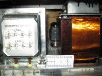
The pic shows how close the mains transformer (can also be smoothing choke) to the p-p o/p tranny is in my amps: in this example a stereo 2x150W full performance into a 19" rack dimensions isn't without its problems and those who haven't experienced this compactness = avoid it !
Generally avoid this iron closeness unless one is quite sure one can deal with mutually coupled unscreened magnetics using sufficient global negative feedback is a powerful weapon; esp so in SE types. So spend some time studying various physical layouts.
Many builders run into trouble by not adhering to the layout basics; keep mains trannies where poss away from other irons and with proper grounding.
All of course O.M.O
richy
The p-p output tranny in theory should cancel the rectification hum on the B+ supply: (not single ended = SE), so for either fixed bias or autobias amps it pays to study different types of rectification systems, i.e cap-input (high peak currents require careful chassis earthing) filtering or inductive input filtering.
In the majority of mybuild amps with relatively tight physical iron layouts, hum will be noticed from the LS on switch on, but as amp warms up this hum is cancelled by the equal currents is each half p-p core and the effect of the global negative feedback loop reduces it to near nil. Generally with p-p types, a much higher AC ripple 100Hz component can be tolerated in the B+ without any problems, so-long the output stage remains in near balance.
How to Specify HT Windings
has a quick looking formulation. There is a raft of software psu design programs available online.
I suggest to get a copy of Morgan Jones, valve amplifiers third ed which treats this in full.
The Radiotron Handbook 4th edition is another mine of information, mostly in imperial.
The pic shows how close the mains transformer (can also be smoothing choke) to the p-p o/p tranny is in my amps: in this example a stereo 2x150W full performance into a 19" rack dimensions isn't without its problems and those who haven't experienced this compactness = avoid it !
Generally avoid this iron closeness unless one is quite sure one can deal with mutually coupled unscreened magnetics using sufficient global negative feedback is a powerful weapon; esp so in SE types. So spend some time studying various physical layouts.
Many builders run into trouble by not adhering to the layout basics; keep mains trannies where poss away from other irons and with proper grounding.
All of course O.M.O
richy
Attachments
how specific (cheekily asking you to be more specific and the specificness)? I have measured it at each stage.
Earthing is by a earthign bus, connected to chassis at one end (signal) and to the psu cap at the other.
The amps on silent on swith on, only when the tubes are conducting (5-8 secs) does the hum build. this makes me think its not transformer pick up, but more likely a local earthing problem, or the B+. 0.75v ripple on the splitter anodes seems a lot.
I agree looking at the scope, but as a relative youngster to this i wanted to see myself. I have now seen.... and will be going to fixed bias (and if anyone has a pot suggestion i am all ears)
but, this doesn't point to the hum.
Running PSUD2 on your published power supply, I got the following result.
Ripple at the splitter was about .74 Vpp
Ripple on the output B+ was about 4 Vpp
My thoughts are
1. Add a small choke and a smaller cap between your rectifier and your first PS cap. Say a 1.5H, 300mA 15 ohm, along with a 50uF .
2. Replace the 100R with 2 50R and add an additional 50uF
I just pulled parts out of the air. See what is available and inexpensive to you.
Doug
- Status
- Not open for further replies.
- Home
- Amplifiers
- Tubes / Valves
- first go at design - pp