magic freq response on 2nd panel - more bass
Well the 2nd panel is waaaayyyy better than the first attempt .
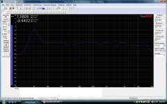
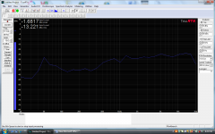
Lowering the tension did the trick 😉, and altering the transformer setup also made for an easier load to drive . - we put a 1 ohm resistor in series with the amp and the freq resonse was very flat to me at 30mm test . at 3 mtrs though , the freq sloped off quite a bit , perhaps this is cancellation ?
The sound is awesome - could listen to it for hours.
Cant wait now to try to build a 3rd panel and tidy up the 2nd . time to look into effect tube amp OP transformer when I see one suitable .
My friend with the test gear and his appogees was pretty impressed.
It has been very interesting to learn about and a rewarding experience - thanks to Charlie Jazzman's website for the shared knowledge and photographs that incouraged me to do this - cheers everyone else that helped also .
Well the 2nd panel is waaaayyyy better than the first attempt .
Lowering the tension did the trick 😉, and altering the transformer setup also made for an easier load to drive . - we put a 1 ohm resistor in series with the amp and the freq resonse was very flat to me at 30mm test . at 3 mtrs though , the freq sloped off quite a bit , perhaps this is cancellation ?
The sound is awesome - could listen to it for hours.
Cant wait now to try to build a 3rd panel and tidy up the 2nd . time to look into effect tube amp OP transformer when I see one suitable .
My friend with the test gear and his appogees was pretty impressed.
It has been very interesting to learn about and a rewarding experience - thanks to Charlie Jazzman's website for the shared knowledge and photographs that incouraged me to do this - cheers everyone else that helped also .
Nice !!!!!! Hope you manage to fix the 1st one as Well and have great night of listening to all ur music 🙂 love that
Hi WrineX - well I pulled the 1st entirely apart - mesh stators not bent or marked at all . actually - amazing , I managed to pass a craft knife down the middle and stay one side of the diapragm all the way to the end and opened it up like a fish. - the film was totally intact. - I will rebuild the 1st to be a mating panel for the 2nd build ( if that makes sense 🙂 . But before I do , im trying to learn about cancellation .. because we have decaying slope at listening position in medium damped room . - or is it cancellation , maybe its the beaming of the highs that make it look like cancelled lows.
this is common for a fullrange esl unsegmented. you could add some baffle to it and see what happens to the lower frequency's, but you will have a slope. and the usually mid range suckout. to be honest it would be a shame to ad allot of baffle. they looks so nice.
maybe some DSP ?
maybe someone who builds unsegmented fullrange esl can shed a light on it.
maybe some DSP ?
maybe someone who builds unsegmented fullrange esl can shed a light on it.
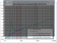
...freq resonse was very flat to me at 30mm test . at 3 mtrs though , the freq sloped off quite a bit … im trying to learn about cancellation .. because we have decaying slope at listening position in medium damped room . - or is it cancellation , maybe its the beaming of the highs that make it look like cancelled lows.
It is the nature of a finite height line source to progressively lose more and more lows the further you move away from it. The acoustic mechanism at work is the beaming of the panel in the vertical direction. For a given line height and listening distance there is a break point frequency at which the sound is no longer tightly beamed by the panel, but starts spreading out in the vertical direction. With the sound power radiated by the ESL unchanged, the portion of that radiated power that gets to you gets progressively less below the break point frequency.
- Moving further from the ESL and the break point moves up in frequency. (ie more bass loss)
- Increase the line length and the breakpoint moves down in frequency. (ie less bass loss)
- If the ESL is placed on the floor, its effect length will be increased 2x to 3x
- If the ESL is floor to ceiling in height, it’s effective height is theoretically infinite and the lows will not vary in level as you move further from the ESL
- If your line source ESL is not floor-to-ceiling in height, you will need to EQ the response for the listening position, and understand that the sound will have less bass if move further away and more bass if you move closer.
More discussion, formulas for calculating breakpoints, and a spreadsheet calculator here:
http://www.diyaudio.com/forums/plan...r-esl-simulator-esl_seg_ui-2.html#post2913884
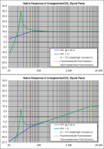
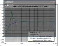
Attachment #1: This is the predicted response of your ESL @ 30mm and 3m using the spreadsheet calculator.
Attachment #2, 3: Scaling and overlaying your measurements, there is reasonable agreement with the trends.
More discussion and examples of acoustic response trends for ESLs here:
http://www.diyaudio.com/forums/planars-exotics/258958-help-esl-simulator.html#post3988441
http://www.diyaudio.com/forums/planars-exotics/258958-help-esl-simulator.html#post3989632
Attachments
Last edited:
Thank you Mr Bolserst - this is interesting - I have tried the simulator a few times , kept it simple and only altered one parameter at a time to see cause / effect . I noted that the width was a key factor in lifting bass level to maintain flat response at 3mtr distance . Perhaps I could be making 2x250mm panels per channel 🙂 - I have enough stator perf mesh , mylar , and foam tape + copper tape to make 4 panels all together . But I dont have enough transformers :-( ..im getting distortion in my eyes ...
Glad to hear you were able to play around with the calculator to get a feel for how the different variables(height, width, listening distance) interact and affect the response.
If all you care about is lifting bass at 3m listening distance, then you are correct that adding width would be the way to go. But having a 50cm – 60cm wide panel will results in increased lateral directivity. With your current 25cm wide panel, you are already experiencing beaming that requires you to listen nearly directly on axis if you want to hear the highs. Doubling the width will cause the beaming problem to reach down into the midrange and make positioning to hear the top octave even more critical.
One fix for this is to divide the width up into several facets of smaller width and then position and angle them along an arc like Acoustat did with their Model 3 and 4, or Sound Lab does with pretty much all their speakers. A more difficult build though, and yes a more difficult load for your transformers.
Alternatively, you can use electrical segmentation where a ladder resistor network is used to effectively increase the driven area as you go down in frequency. This also has the benefit of equalizing the falling response you experience when driving the whole panel with the same signal. Again, a more difficult build, but happily an easier load for the transformers.
One other thing to consider when adding that much width instead of height is that you will be compounding the tilting of the frequency response with changing listening distance. Instead of just a low end change from the height break point you will also see a top end change since the width break point is now well into the audio range.
busy busy as a bee
Thanks for your input as always - I am amazed at the true effort people kindly share . I guess I help people in the industrial electrical field without thinking , but here , a hobby , - the sharing of the knowledge / experience is overwhelming . I only get Sundays off to work on these things , I intend to build a replica of the 2nd panel ( less tension , hori spars ) .. and place beside the 2nd panel . - but attempt to mask the HF from the 2nd panel leaving to drive below 750 hz below ... Again , thank you from NZ to USA .
Thanks for your input as always - I am amazed at the true effort people kindly share . I guess I help people in the industrial electrical field without thinking , but here , a hobby , - the sharing of the knowledge / experience is overwhelming . I only get Sundays off to work on these things , I intend to build a replica of the 2nd panel ( less tension , hori spars ) .. and place beside the 2nd panel . - but attempt to mask the HF from the 2nd panel leaving to drive below 750 hz below ... Again , thank you from NZ to USA .

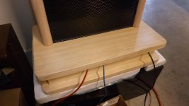
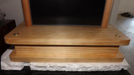
Time to finalise support for the panels and enclose the transformers in the base compartments I think ..more wood work to come .
Hi. Really cool!🙂🙂🙂🙂🙂
looks like that is not a problem for you. 🙂 all the wood in the background and ofcourse how they look already! nice!
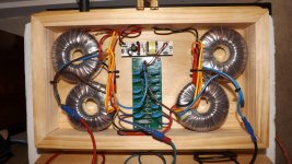
Seasons greetings & thanks Jerald -the info is a bit misleading .. I meant to say , ive configured it for the lowest level of output , but the esiest on the amplifier. - the 6v primaries are all in series ( 24v into 4 x 230 ) so 24v into 920 , which is like 1:38 . - but your figure I am confused , as this would be 1/2 the calc'd value of 6 into 920 ( which should be 153 ) ... 76 being half . So now I know you calcd it different way .. is this because we only calc one half , because of the center tap , and the ratio is spilt across the d/s ..which is only the diaphram and ONE stator ? - if this is so then my true setup at present is 1:19.1 ?? - seems too low to make output . yet it works fine for my office . Im purely trying to increase the resistive load on the OTL ..as the primaries are about 0.4 - 0.5 ohm .
Ooooh Okay!!
I was thinking that the four cores were for both sets of panels at 6/460 each.
Sorry for the confusion. 😉
Your ratio is 1:38.33 as you calculate it for the voltage across both stators not just one.
jer 🙂
I was thinking that the four cores were for both sets of panels at 6/460 each.
Sorry for the confusion. 😉
Your ratio is 1:38.33 as you calculate it for the voltage across both stators not just one.
jer 🙂
- Status
- Not open for further replies.
- Home
- Loudspeakers
- Planars & Exotics
- First ESL build - Full Range .