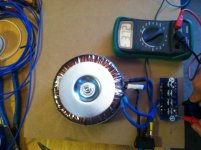
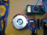
It seems that things are starting to come together here. Transformers arriving on Thursday hopefully. I chose two 330VA 25v + 25v 😀
I practiced soldering with a radio-shack kit. After a little practice things were begining to look good.
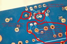
Then on the LM3875, my first couple of joints didn't turn out so well. They just look a little gritty and dull. It is difficult to photograph shiny things, but the others look mirror-chrome-like shiny, so that's good
I tried to reheat/reflow the two that look dull, it seemed to make it worse, so I stopped messing with it. They look a little better now that I have scrubbed off the rosin stuff, not too gritty anymore, but not as shiny as the rest. Should I remove the solder with a wick, and then start over?
There is one place that I have created a solder bridge, but I think that that part of Rf and R3 on the board are connected anyway, right?
Board around pin 11 on chip started to melt, but I don't think too bad. I don't think there is much I can do about it now.
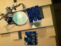
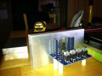
So here is a macro 1:2 photo. Be nice (and honest), it's a close up, and my first try after practicing with only a couple dozen or so LED's and resistors from Radio Shack.
p.s. I highly reccomend this little magnifying glass thing. My eyes are getting old, and this thing was only $4. Not highest quality, the arms are hard to lock into a position, but I only use the glass part anyway.
More to follow soon next week or two. I think you'll like my concept and design for chassis!
AlexQS
I practiced soldering with a radio-shack kit. After a little practice things were begining to look good.
Then on the LM3875, my first couple of joints didn't turn out so well. They just look a little gritty and dull. It is difficult to photograph shiny things, but the others look mirror-chrome-like shiny, so that's good
I tried to reheat/reflow the two that look dull, it seemed to make it worse, so I stopped messing with it. They look a little better now that I have scrubbed off the rosin stuff, not too gritty anymore, but not as shiny as the rest. Should I remove the solder with a wick, and then start over?
There is one place that I have created a solder bridge, but I think that that part of Rf and R3 on the board are connected anyway, right?
Board around pin 11 on chip started to melt, but I don't think too bad. I don't think there is much I can do about it now.
So here is a macro 1:2 photo. Be nice (and honest), it's a close up, and my first try after practicing with only a couple dozen or so LED's and resistors from Radio Shack.
p.s. I highly reccomend this little magnifying glass thing. My eyes are getting old, and this thing was only $4. Not highest quality, the arms are hard to lock into a position, but I only use the glass part anyway.
More to follow soon next week or two. I think you'll like my concept and design for chassis!
AlexQS
Attachments
I also practiced with radioshack parts. Great idea!
What kind of solder are you using? Any pics of the enclosure?
What kind of solder are you using? Any pics of the enclosure?
I also practiced with radioshack parts. Great idea!
What kind of solder are you using? Any pics of the enclosure?
No pics of enclosure yet.
I'm using Kester rosin-core SN63PB37 0.020" It is much easier to work with then the other solder I have, I think because of the small guage, and because it contains led.
I also have some Cardas Tri Eutetic, but it's 0.031" led free. It is just too big to use on the pcb's, but I'll probably use it for the cross-overs in the speakers that I'm building.
I have a small package of 0.050" silver solder that I got for cheap from a hardware store. Great for tinning a new solder needle.
AlexQS
Rf and R3 on the board are connected anyway, right?
Board around pin 11 on chip started to melt, but I don't think too bad. I don't think there is much I can do about it now.
AlexQS
Yes they appear to be connected on the board. (And from memory)
The burn around pin 11 looks like it might be just burnt rosin flux, which is a little more stubborn to clean. That's what it "looks" like from here.
The rest look good, I would visually recheck the rest and not subject the chip to anymore heat unless needed.
Wow, you really have chosen overkill with those transformers. That's fine and won't do any harm, but you are going to get about 44V on each rail from them. That is at, if not beyond, the limit of what a 3875 can take. Up on the limit is not a good place to be anyway, but it's worse in your case because it's hardly going to fall by much under load.
I would suggest that you have to lose some voltage somewhere. Two easy ways, both of which are nominal improvements, are to have two bridges - one for each half of the supply and possibly split the reservoir caps with a resistor. Otherwise I would suggest a regulated supply or at least a cap multiplier that can knock off a few volts and give you the proper voltage. The voltage you need will depend on the load of your loudspeakers but I would suspect that 37V is probably the sort of region you would need to be looking at for a general design with a 3875.
I doubt that the 3875 will blow on 88V unloaded (its absolute limit is supposed to be 84V) but you will need a proper sized heatsink to keep it out of trouble and stop its protection kicking in.
The other thing you could do is to "unwind" a few turns on the transformer. This is not to actually unwind them, but to wind reverse turns on each side so you get a lower voltage. To gauge how many turns just wind 20 turns around it, anywhere, and read off the voltage you get. Then, in the right direction, take a tap off the output, and backwind the unneeded turns.
Hope this helps and hasn't frightened you too much.
Christian Thomas
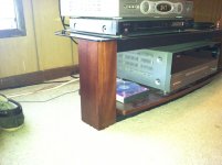
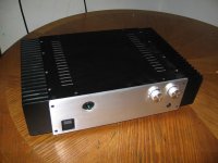
@ SoIL4X4 - This may give you an idea of the chassis plan I have in mind. I want something very solid. When I was a kid we had an integrated with a chassis made of ceramic. I guess I was "sold" on the idea of having something that doesn't vibrate much. I have poured concreet sidewalks around my home, and thought it would be within my capabilaties to make a "shelf" to mount the components to. Perhaps I would use a concreet "Paver Tile", or maybe a thick "Marble Tile" (depending on cost). Below is a photo of my stereo stand. Imagine two (1 left and 1 right) "End Tables" or "Night Stands". I will have two "Shelves" between 4 wooden legs of each table. -It will match the stereo stand and be the same height, with a glass top. One shelf will have the transformer and rectifier board. I will make a nice embelicle cord (I have a nice sheath + heatshrink tube, etc) to connect to the amplifier pcb on the other shelf. -Might sound silly, but I think it will match my furniture, and I'll finally have a place to set the remote controll, LOL.
@ Christian -I was hoping to be right around 37volts per rail, I read somewhere that is ideal. I don't know how to calculate it, but I think I should be close to that. I know many people go for a 300VA 22v + 22v. I am hoping to get a little more detail depth in the sound stage by being at a higher voltage. Mind you that I would never connect anything less than an 8 Ohm speaker.
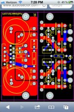
@ Globug. Thanks for checking out my pics. I thought that Rf & R3 were connected anyway. It makes my consciouse feel at ease when I double check with someone. -I picked up some hardware, nuts, bolts, a tap/die thing, and heatsinks today. They are 3" x 6" x .75" aluminum, I think it should be sufficient, but I will monitor their temp. Surprisingly inexpensive. I am going to polish them up real nice, then take them to a machine shop, and have them "Rabbet" or make a step/ledge on each side, so that the ends are thin enough that I can drill hole for RCA on one end, and Speaker binding post on the opposite. My stand-offs are 1" tall, so I'll have room to put a fat wire from the underside of the board at OG, and connect the other end to chassis. Then I'll solder wires to the center of that fat wire to get PG+ & PG-& Speaker Ground stared to the same point.
@ Christian -I was hoping to be right around 37volts per rail, I read somewhere that is ideal. I don't know how to calculate it, but I think I should be close to that. I know many people go for a 300VA 22v + 22v. I am hoping to get a little more detail depth in the sound stage by being at a higher voltage. Mind you that I would never connect anything less than an 8 Ohm speaker.
@ Globug. Thanks for checking out my pics. I thought that Rf & R3 were connected anyway. It makes my consciouse feel at ease when I double check with someone. -I picked up some hardware, nuts, bolts, a tap/die thing, and heatsinks today. They are 3" x 6" x .75" aluminum, I think it should be sufficient, but I will monitor their temp. Surprisingly inexpensive. I am going to polish them up real nice, then take them to a machine shop, and have them "Rabbet" or make a step/ledge on each side, so that the ends are thin enough that I can drill hole for RCA on one end, and Speaker binding post on the opposite. My stand-offs are 1" tall, so I'll have room to put a fat wire from the underside of the board at OG, and connect the other end to chassis. Then I'll solder wires to the center of that fat wire to get PG+ & PG-& Speaker Ground stared to the same point.
Attachments
25v times 1.4 = 35v, not 44
He's right on the money.
Thanks. It seems I am learning more and more how to calculate things.

AlexQS
Apologies. I am absolutely wrong. I have two 300VA transformers here and thought they were both the same voltage (at 25V) and the supply I built was giving me +/- 44V. In fact that one is a 30V transformer (which I feel sure I never ordered).
Since one can never quite predict how these things turn out, forward V drops and losses etc. so never quite x root 2, I didn't bother to even do the mental arithmetic and just posted from experience.
So you will be fine. But get yourself a decent soldering iron. I use a Solomon ceramic station which is about £40 but they come under all sorts or names and one without a station can be had for about $12. Makes all the difference.
if you model it correctly you can predict fairly closely.............Since one can never quite predict how these things turn out, forward V drops and losses etc. so never quite x root 2,.........
That's the basis of software simulators. There is nothing wrong with pencil, paper and mental arithmetic.
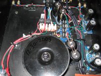
One working power supply
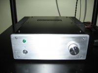
This is progressing slower than I thought. And my cool idea for chassis will come later, just a peice of wood to get this thing working first.
I think this is perfect! I had read somewhere that 37 volts is ideal; and that was my goal. Also I'm glad that V+ and V- are the same; I almost expected them to measure differently, but I believe they are the same because I omitted the diode from P.Daniels power-supply pcb. (???)
I used my start-up-test-lightbulb in series with live mains that I made. It did not light up at all.
At first I was not getting any reading with voltage meeter, I began to feel upset, then I realized I had forgoten to install the fuse in the IEC powerjack. 🙂
Yay it works!!!😀
Attachments
Nice, now you just need to try to change those tiny 10uf power supply caps for "real" power supply caps.
Indeed, I do plan to. Doing one thing at a time. I really want the experience of hearing it one way (for a couple weeks or so) then changing it and hearing the difference.
This whole thing is so much fun!!
🙂
This whole thing is so much fun!!
🙂
.....but I believe they are the same because I omitted the diode from P.Daniels power-supply pcb. (???)
Edit: this should read "LED". You guys probably knew I was talking about the one that emits light.
Indeed, I do plan to. Doing one thing at a time. I really want the experience of hearing it one way (for a couple weeks or so) then changing it and hearing the difference.
This whole thing is so much fun!!
🙂
Good to hear that! The fastest way to check it is by using alligator jumpers. just leave the tiny 10uf caps on board and then jump them with big caps using the alligator jumpers!. I did the LM3875 (Audiosector) about four years ago too and trust me when I say you will "feel" the difference with big capacitance (at least 10.000uf per rail). Good luck and post pictures when it is done 😉
What does "per rail" mean? Is that like V+ to PG+ is one rail, and V- to PG- is the other? Or does it mean the left channel is one and the right is the other?
Also should I be counting the two 1500uF caps on the amp-pcb as included in the 10000uF?
Also should I be counting the two 1500uF caps on the amp-pcb as included in the 10000uF?
Just see your post #11 with pictures you read one rail and than the other rail. you can take that 10uf and use two 4.700uf or 6.800uf or just one 10.000uf and do the same with other rail (V-,V+)


- Status
- Not open for further replies.
- Home
- Amplifiers
- Chip Amps
- First build, Dual-Mono LM3875