Hello everyone,
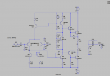
While I'm still waiting for parts for my BX-500 repair project, I thought I'd try to build an amplifier from leftovers, the sediment of the workbench, so to speak. The catch is, I don't seem to have a power PNP anymore, so I thought I'd try a quasi-complementary power amplifier with the good old 2N3055 and BD139/BD140 as drivers. The IPS consists of a few 2N5551/2N5401 I still had available.
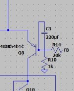
I played around a bit with LTSpice and basically got along quite well, but I have problems with the biasing of the output stage. My problem is still my VAS / VBE multiplier stage. Somehow I can't get the lower PNP Q3 to get its -700mV properly while Q4 is biased to 1.4V. The voltage drop of 2.1V over the VBE multiplier is about right, but the potential of the VBE Multiplier is too high, the lower side of the VBE multiplier is at +700mV, the upper one is 1.4V too high.
I think the problem is probably easy to see & solve for an experienced audio hobbyist, but this is my first own amplifier design, and I just can't find the error 🙂
I am aware that the 2N3055 is not a high end transistor and the result of this tinkering is not a 0.0000000001% THD Ultra Hifi amplifier, but I just want to try to build something out of leftovers, and if something goes wrong it's not that tragic. The Output Zobel Network and Fuse isn't attached right now, a load isn't either.
The schematic as PNG and Spice-File can be found in the attachments
Thanks a lot for your help!
Best regards
Lukas
While I'm still waiting for parts for my BX-500 repair project, I thought I'd try to build an amplifier from leftovers, the sediment of the workbench, so to speak. The catch is, I don't seem to have a power PNP anymore, so I thought I'd try a quasi-complementary power amplifier with the good old 2N3055 and BD139/BD140 as drivers. The IPS consists of a few 2N5551/2N5401 I still had available.
I played around a bit with LTSpice and basically got along quite well, but I have problems with the biasing of the output stage. My problem is still my VAS / VBE multiplier stage. Somehow I can't get the lower PNP Q3 to get its -700mV properly while Q4 is biased to 1.4V. The voltage drop of 2.1V over the VBE multiplier is about right, but the potential of the VBE Multiplier is too high, the lower side of the VBE multiplier is at +700mV, the upper one is 1.4V too high.
I think the problem is probably easy to see & solve for an experienced audio hobbyist, but this is my first own amplifier design, and I just can't find the error 🙂
I am aware that the 2N3055 is not a high end transistor and the result of this tinkering is not a 0.0000000001% THD Ultra Hifi amplifier, but I just want to try to build something out of leftovers, and if something goes wrong it's not that tragic. The Output Zobel Network and Fuse isn't attached right now, a load isn't either.
The schematic as PNG and Spice-File can be found in the attachments
Thanks a lot for your help!
Best regards
Lukas
Attachments
Last edited:
Well, that was simple!
Thank you very much!
Are there other (obvious) mistakes, or can I try to build it?
Thank you very much!
Are there other (obvious) mistakes, or can I try to build it?
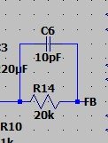
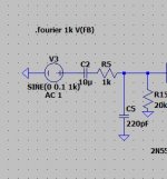
An input filter would be sensible.
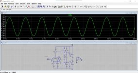
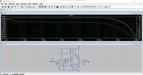
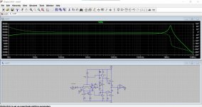
The response is very peaky at HF and needs taming. In simulation a 10pF works OK but be prepared to experiment a little.
The response is very peaky at HF and needs taming. In simulation a 10pF works OK but be prepared to experiment a little.
Attachments
After getting an 10pF Cap, I build the Amp on a piece of perfboard, and it seems to work nicely! Thanks a lot! Sadly, I don't have any pictures, it's already built into a friend of mine's little bookshelf speakers (built it twice) to make them active!
Maybe I'm going to build a few more Amps with this Dinosaur-Transistor 2N3055, I just found 30 NOS 2N30555 from OnSemi in a pile of parts in my grandpa's workshop ...
Maybe I'm going to build a few more Amps with this Dinosaur-Transistor 2N3055, I just found 30 NOS 2N30555 from OnSemi in a pile of parts in my grandpa's workshop ...
After getting an 10pF Cap, I build the Amp on a piece of perfboard, and it seems to work nicely! Thanks a lot! Sadly, I don't have any pictures, it's already built into a friend of mine's little bookshelf speakers (built it twice) to make them active!
Maybe I'm going to build a few more Amps with this Dinosaur-Transistor 2N3055, I just found 30 NOS 2N30555 from OnSemi in a pile of parts in my grandpa's workshop ...
That's good 🙂 Pleased to hear it's working well.
Connect a diode shunted with a 100 ohm resistor to the emitter Q3(BD140).
But you didn't say why...
🙂
Help in design: adding a Baxandall diode across emitter in Quasi Complimentary Stage
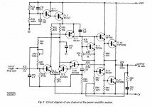
Here is an interesting Quasi design from the 1970's. Single rail but it had a couple of unusual aspects to it. I've built this years ago and thought it sounded very good. The omission of any emitter resistors on the outputs might be worth looking into for better thermal stability.
Attachments
Connect a diode shunted with a 100 ohm resistor to the emitter Q3(BD140).
Audio Power Amplifier Design Handbookbooks.google.ru › books
A major improvement to symmetry can be made by using a Baxandall diode[8], as shown in Figure 6.5c. Placing a diode in the driver circuit of the CFP (lower) ...
Douglas Self -
- Home
- Amplifiers
- Solid State
- First Amplifier Design / Darlington + CFP Biasing Problem