IT Coupled Schema
For now I'll stay away from the CF. Save that for a later experiment.
The 6h30 certainly would drive the 300 and the curves look great, but does it have enough gain with a mu=15? The LL1671 is also interesting especially a lower Rp tube. Am I right in this case to assume that I want to keep impedance of the IT around 3-4 of Rp?
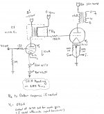
Attached is a schema of IT coupled amp. It is Very simple as was said by others before and with LED cathode bias on driver can eliminate almost all cap in signal (except PS). In it I again proposed the use of the 5965. Running the triodes in parrallel the Rp would be 3600ohms. Only problem here is that with the LL1660 /10 would have to keep current on light side. Could have it gapped for higher mA.
I am not attached to the 5965 just kinda use to their numbers for the mu range I was looking for. mu=47
In the circuit assume standard 300b operating point for now.
At this point in the game I am looking at pretty much custom iron so anything goes within reason. And YES I will build it. With your help I have come too far not to.
For now I'll stay away from the CF. Save that for a later experiment.
The 6h30 certainly would drive the 300 and the curves look great, but does it have enough gain with a mu=15? The LL1671 is also interesting especially a lower Rp tube. Am I right in this case to assume that I want to keep impedance of the IT around 3-4 of Rp?
Attached is a schema of IT coupled amp. It is Very simple as was said by others before and with LED cathode bias on driver can eliminate almost all cap in signal (except PS). In it I again proposed the use of the 5965. Running the triodes in parrallel the Rp would be 3600ohms. Only problem here is that with the LL1660 /10 would have to keep current on light side. Could have it gapped for higher mA.
I am not attached to the 5965 just kinda use to their numbers for the mu range I was looking for. mu=47
In the circuit assume standard 300b operating point for now.
At this point in the game I am looking at pretty much custom iron so anything goes within reason. And YES I will build it. With your help I have come too far not to.
Attachments
Latest Revision
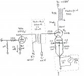
Attached is the latest. Have had quite the discussion with Jack at Electra-Print. And with his thoughts, which parallels much of what has been said here, the following was established as a base point.
The design is two stage with I.T. The driver is a 437a / 6S45pi. Either one will give low impedance out with enough gain. I decided to stay with a triode at this point of my learning curve. I have a lot to learn first before I play with pentodes. I have some 6s45pi on order and am looking for a 437a. I am aware that they are not a drop in replacement and that the 6s45pi will require careful attention to avoid oscillations.
The I.T. is as low of an impedance as possible with the driver tube and will be gapped for 25mA. (I could go to 35mA with a larger core. My concern, which is probably incorrect, is that the larger core would impact higher frequency when used at lower currents. I want to start out conservative. However if my concern is wrong then will go to larger it from the get go. I in no way shape or form have a good understanding of transformers.
The OPT is a comprimise based on the different speakers I have. I picked a 4k primary with 6 ohm secondary gapped for 80mA. This will be Jack's partial silver design.
Now for the power supply. I think it would be best to use a similar design as the SJS Monoblock. The link is in a previous post. The difference being I would like to break it into a least two PTs. One for the rectifier, B+ and 300B filament, The other for the B'+ and C- and associated filaments and rectifiers. That way I can get the driver stage and 300b bias up first and then bring on the 300B. I would use a similar relay as in the SJS to prevent the 300b B+ from coming on before the bias is at potential.
The 300B B+ would be a CLCLC with a load resister designed to shunt 25% or so of the supply current.
For the Driver B'+ I was thinking of a CLC with a Salas voltage regulator.
For the 300B bias, C-, I am still open for ideas. I was thinking that a CLC with a Salas Regulator would be good, but my concern would be with mains voltage fluctuation causing variability in the bias point due to the unregulated B+. Maybe it wouldn't be an issue so open to feedback. I also considered using a regulator on B+ but the thing would probably end up with more heatsinks than my Aleph X.
My filaments will be regulated DC using a lm317 set-up for high ripple rejection.
Any thights?
Attachments
For the 300B bias, C-, I am still open for ideas. I was thinking that a CLC with a Salas Regulator would be good, but my concern would be with mains voltage fluctuation causing variability in the bias point due to the unregulated B+.
Any thights?
IMO a simple CLC bias supply is good.
If you have a regulated bias supply and unregulated anode supply it is possible to run the tube very hot. For example: you have decided for 375V on the plate and approx. -79V for 70 mA which is a good one. At some point the line voltage increases a little bit, your plate voltage will increase, say 15V, while you bias will not change significantly so that the anode current will jump to 90-100 mA!
On the contrary if the line voltage drops, the current will drop quickly.
If the bias is unregulated: when the anode voltage increases the bias will decrease accordingly (because it increases in absolute value but is negative respect to ground). So you are safe. Idem if the line voltage decreases.
I don't have good experience (i.e. I don't like how it sounds) with regulated anode supply for power tubes. If the amp has enough headroom I think you will not be able to detect any change due to the line voltage, unless this is really big.
Thanks.
Will start with a CLC then. Unregulated. Is there a good rule of thumb for sizing the P.T>? The 300B will need 70mA, if I size it for lets say 150-175mA would it hurt other than in the pocketbook. To me, having that kind of oversize will keep it cooler and have a lower source impedance.
Is there way to get PSU2 to accept both a resistive load and a current sink?
In regard to line voltage, I don't really know what its range is. If it varies quite a bit then I suppose the easiest thing to do is put in a decent line conditioner on that circuit. That way all of my equipment would see a better mains.
Then specify the actual VA (accounting for drops in the OPT, chokes etc..) together with the a lower current density for the windings of your PT and a lower induction.Thanks.
Will start with a CLC then. Unregulated. Is there a good rule of thumb for sizing the P.T>? The 300B will need 70mA, if I size it for lets say 150-175mA would it hurt other than in the pocketbook. To me, having that kind of oversize will keep it cooler and have a lower source impedance.
For E+I core types the average working conditions, I think, are calculated for B=10-11000 Gauss and ρ=2-2.5 A/mm2 to save on core size and copper. You can specify B=9000 Gauss and ρ=1-1.5 A/mm2. In this way you will get your voltages under full load, based on the correct turn ratio, with lower winding DC resistance and lower induction (that typically results in lower leakage flux). Also, you want to decide the type of rectification in order to know the AC values and the types of winding (i.e. how many leading wires).
In regard to line voltage, I don't really know what its range is. If it varies quite a bit then I suppose the easiest thing to do is put in a decent line conditioner on that circuit. That way all of my equipment would see a better mains.
Typically the variation is around 5-6%. However in some places can be +/-10%. Usually the supplier has to specify this by law somehow/somewhere.
I would not be worried about it. Add the conditioner if you like .
Last edited:
Power Supply Version 1
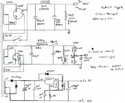
Attached is the first wack at the power supply. I will claim no originality here. I stole stuff from everyone it seems. It has been modeled through PSUDII. The values I chose took the approach of minimizing response time to current changes without ringing.
Simulated ripples voltages are stated at the respective current.
I have a second version with higher capacitor values that have slightly lower ripple but with settleing times 4 to 5 times the length.
I am not sure what would be best for a SET. Plenty of opportunity for test and measure.
The 300b filament supply is silicon rectified and regulated using a lm317 set up for high ripple rejection. Per the spec this should have 80db rejection.
The Driver Power circuit is not listed yet but will be at least a CLC or possibly a CLCLC to drop ripple down further, since its noise will be amplified the most.
I have been reading the last several days but have yet to come up with a good % for ripple. What levels should I be shooting for.
Attachments
Nice C- supply. I like the relay coil application there. Possibly a free wheeling diode across the coil to control reverse spikes ?
I would suggest a resistor (maybe 100k) from the wiper of the pot to the negative rail as belt and suspenders.
I would suggest a resistor (maybe 100k) from the wiper of the pot to the negative rail as belt and suspenders.
Good point. I was trying to figure that problem out the hard way like trying to get the relay to drop out. (Way too much thinking with no benefit) Simpler is better. Resistor is added.
I can't claim the relay as my idea. I used the SJS design but put the contacts into the filamanent power for the rectifier instead of directly in the b+ circuit. In both cases the relay is at B+ potential, but now the B+ comes up slow.
I can't claim the relay as my idea. I used the SJS design but put the contacts into the filamanent power for the rectifier instead of directly in the b+ circuit. In both cases the relay is at B+ potential, but now the B+ comes up slow.
FYI: I've been told by many that the LM317 series regulators aren't quiet enough for DHT supplies, you may be dissapointed.
FYI: I've been told by many that the LM317 series regulators aren't quiet enough for DHT supplies, you may be dissapointed.
The LM317 will be fine, especially with the bypass cap across the resistor from adj to ground. There's plenty of people who run DHT tubes from AC supplies without issue. Tubes that are sensitive to filament hum tend to be very high mu transmitting tubes like the 811A. I run 845s on 10vac filaments with a hum balance pot and its only noticeable with your head against the speaker.
SGregory: How goes the project? Did you actually order those Electra-Print transformers? What do you think of them? Which load impedance and bias point did you end up with for the 300B?
I'm considering upgrading to the Electra-Print transformers for my design, hence my question.
~Tom
I'm considering upgrading to the Electra-Print transformers for my design, hence my question.
~Tom
Tom,
The project is on hold for the moment. I need to see if I can make a 6c45pi stable outside of its cardboard box first. Have been working on my analog source recently and am about to start a new thread on a Gyrator loaded 12b4a if it sounds as good as it measures. (Not always the case as you know. Am getting 0.01% THD with a -130dB noise floor.)
I have ordered several Electra-Print PT's, Chokes, and OPT's and have never been dissappointed. They are not fancy but are solid and have excellent sound. If you are refereing to the interstage xfmr I am comfortable with Jack's skills and would trust them as well. They are not too expensive unless you go exotic.
Last edited:
I'm currently using Edcor transformers (CXSE25-8-5K) but am not terribly thrilled with them. For low powers, they're good bang for the buck. But the 300B should be capable of delivering over 10 W with 3k load when run close to the max plate dissipation. Some playing with the plate curves and paging around in RDH4 suggests that 10.8 W @ 3.5 % THD should be possible. Of course, that's with an ideal output transformer.
~Tom
~Tom
- Status
- Not open for further replies.
- Home
- Amplifiers
- Tubes / Valves
- First 300b Design, Please comment