I understand, this is why I have a legal copy of excel 2003 🙂MY computer has Office 2016. There are some issues for which i cannot use J. Bagby's Response modeller.
Anyway VituixCAD, which is free, should have all the tools needed for your scope.
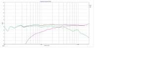
This looks better than before, but it is probably based on bad data again (no phase, incorrect base FR), so it is not a valid simulation.I tweaked the crossover to cross the mid to tweeter to reduce the crossover point from around 6 khz to 3.2 khz.
I don't think so. You have done a good job, but I suggest you to address the faults at the base before doing another simulation. In other words you have to add the baffle effect to the mfg curves (they are all on an infinite baffle), and then in XSim use the phase (there is a button for that called "derived"), and also use an appropriate delay for the mid compared to the tweeter (a value of 0.75" or slightly more should be correct). Also trace the impedance from mfg curves and again in XSim use the derived phase. While not perfect you will be in a ballpark.I Am not good at simulation.
IMHO your choice is based on some debatable assumptions. First, that a first order crossover has some advantage over higher order crossovers. The problem is that in a crossover design the only important slope is the acoustic one you will create, the electrical order is only a technicality. The second problem is that a series crossover works only all together, whereas in a parallel crossover you can tune one driver at a time, and for a novice this can be easier, moreover with a 3 way. And if you want to measure the FR, with a parallel crossover you can easily measure one driver at a time.If i remember correctly Rod said there may be advantage(may be little) of series crossover if considered in case of first order over parallel. Correct me if i am wrong.
Ralf
I think you are referring to the figure 8 in the linked page. However IMHO this is not what the FR of that driver should be on normal 10.5" baffle. It should have instead a constant rise of 6dB from 100 to 800 Hz (more or less), whereas I see a flat FR in that range.Actually I have taken the woofer spl curve from Falcon -III speaker which was designed by Amplab. Peerless 830869 has around 90 db sensitivity. The measurements I followed was giving around 85-86 db. In Falcon-III the same woofer was mounted in a 10.5 inch wide baffle and measured. My build will have a 9.8 inch wide baffle. So I guess baffle step loss is already taken care of. Here is the link of the page
Another mistake you are doing is to use SPL from different and potentially not trusted sources. This is why I suggest you to trace mfg FR, at the least the SPL should be more comparable.
Ralf
Good point there about using manufacturers data for your graphs.
Reading the linked Amplabs page suggest low frequencies are nearfield so have been spliced to give final response suggesting that baffle step has been already accounted for.
Therefore you will definitely need to apply baffles step in your design.
Depending on where you position the speakers in the room against wall, in corners or out into the room you may have to eventually lessen the 6dB attenuation by unwinding turns of the bass inductor. Its a tuning adjustment that can help fine tuning in the final stages
I do not know how a baffle step attenuated response could be called RAW response������
Personally I think it should be fine as a speaker, the driver choices are not a disaster by any means and if they are easily attainable so be it. 🙂
The crossover once knocked into shape should make it a very good speaker.
You have established a flow of good information, so everything should work out with people here helping. The basic elements of the design and the separate mid treble enclosure gives you an extra amount of flexibility for tuning.
The acoustics of the room are going to play a big part as well if it is a modern apartment/condo with solid walls and floors you may need to play with the responses or add additional soft furnishings etc. But that's another topic and an art in itself.
Last edited:
As an example of what a baffle will do to a 8" driver look at the following image. I have simulated a 10"W 36"H baffle with a driver at 8" from top, different values will yield a somewhat different curve. You have to add these values to the mfg curve. Clearly the Amplabs curve you are referring to doesn't exhibit the 6dB loss toward the low frequencies, so it is wrong. How much baffle step you need to compensate depends on the room placement and unless you have a very large room usually is less than the full 6dB loss.
Ralf

Ralf
Attachments
I am going to play and get familiar with Vituixcad. Thank you guys ... You are great and very helpful.
I was thinking about how is it possible to bypass the modelling and baffle step correction thing. I thought of the following plan. Correct me if i am making some more mistakes.
Baffle width 9.8 inch = Baffle step around 465 hz.
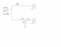
I will design a passive line level crossover (1st order) around 400 to 450 hz. This crossover is dependent on input impedance of Amp or preamp. I Am going to biamp the system. The Lows below crossover point will go to woofer. The highs above crossover point will go to Mid-Tweeter section. The midrange and the tweeter assembly will have a passive crossover circuit of its own(see below).
The problem will be as far as i think is to equalize the spl levels of the woofer and mid-tweet assembly. What more could trouble me ? What do you guys think?
Here is the Mid-tweet crossover
and link to passive line level crossover
TLS.org | Passive Line-Level Crossover
Baffle width 9.8 inch = Baffle step around 465 hz.
I will design a passive line level crossover (1st order) around 400 to 450 hz. This crossover is dependent on input impedance of Amp or preamp. I Am going to biamp the system. The Lows below crossover point will go to woofer. The highs above crossover point will go to Mid-Tweeter section. The midrange and the tweeter assembly will have a passive crossover circuit of its own(see below).
The problem will be as far as i think is to equalize the spl levels of the woofer and mid-tweet assembly. What more could trouble me ? What do you guys think?
Here is the Mid-tweet crossover
and link to passive line level crossover
TLS.org | Passive Line-Level Crossover
Attachments
The problem with the baffle step effect is that in the case of a rectangular baffle the transition from 4pi to 2pi is not gradual. If you look at the last figure I posted you can see that in this example there is a large bump of 2dB between 500 and 1500 Hz more or less, something you need to address with every crossover, active or passive. The only way you can go away doing nothing would be in the case of a natural hole in the FR of the driver with a more or less reversed shape of the baffle step bump. For me this worked once, however the Peerless woofer doesn't have this "feature".
So to recap you need to model anyway. The line level crossover you are thinking will not address the baffle step bump, so IMHO is not the best and more effective solution, doubling you amps without fully correcting the diffraction. If you want to follow the active route you need to choose a programmable digital crossover, but for a crossover point between 400 and 500 Hz it doesn't make much sense economically.
Ralf
I was looking at the figure you posted and I also thought may be modelling is the only resort I am left with
I tried to use Jeff Baby's response modeler. In the impedance modeling section do I need to important . Zma file which is traced from manufacturer published curve or it will be generated automatically? The second thing I find problematic is when I extract minimum phase .frd and .zma, I don't see a valid impedance curve while using them to simulate crossover in Xsim. I followed Paul Carmody's writing how to design a speaker without measurements. Here is the link
Paul Carmody's DIY Speaker Pages - Simulated Measurements pt1
Am I doing something wrong?
Paul Carmody's DIY Speaker Pages - Simulated Measurements pt1
Am I doing something wrong?
In .dxo's you have sent so far, it can be seen that frd's and zma's lack phase data. XSim can also derive phase if you check the box in each driver.
Have a look at FRD Response Blender tutorial. There you can work on your frd's to prepare them fully for a simulation.
edit: whenever you work in RM on your zma, it is best that you model it using its functions and as a template of your final driver impedance, use a traced graph. Once the modeled and traced curves overlap nicely, you are done. This finished model of impedance can then be saved, and it contains both magnitude and phase, thus not needing any further work.
Last edited:
I really like all the work that Paul C has done over the years but his instructions here on impedance sort of miss 1 of the finer details involved.
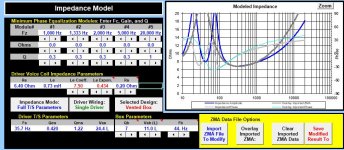
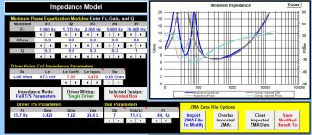
Pic 1 below shows that yes indeed Response Modeler simulates the driver's impedance in whatever alignment you choose, the blue trace. Unfortunately it also shows that's it's only half correct - the grey trace is the measured impedance of the driver imported from the spec sheet. So when you put the driver into a box, not only are you changing the response in the low frequencies, you are also changing the impedance in the low frequencies too. But in both cases, it's only the LF responses that are changing. So the simulated impedance response (blue) is correct in the LF's but incorrect in the HF's. Or to put it another way, the infinite baffle spec sheet impedance (grey) is correct in the HF's but incorrect in the LF's once you put it into a box.*
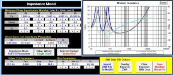
What to do? In the case of the FR, we splice. In the case of the impedance, we manipulate. Pic 2 shows the effect on the simulated impedance of changing the Le Exponent value. Now we've got much better alignment between the 2 curves above about 200Hz but there is still room for improvement.
Pic 3 finally gives me what I want by using just 1 of the 5 equalization modules also included in this section and by just tweeking the Le Exponent a tiny bit more. Now your simulated impedance curve is both correct below 200Hz and above it. Save the modified result and you are good to go.
One other comment on Paul's impedance instructional: Sure it's a good idea to include xo series resistance in the box modeling because it will indeed alter the response just a little bit, but think about it, if you include it here in the impedance as well, then when you use that file in your xo sim and then add in the series xo components with their resistance values included, you are effectively adding that resistance value to the driver's impedance twice. So I include it when I save the modeled box FR but I don't include it when I save the modified box impedance curve.
* For a little more detailed explanation, hover your cursor over the little red triangle in the Le Expon. cell and/or have a closer look in the User Guide tab.
Pic 1 below shows that yes indeed Response Modeler simulates the driver's impedance in whatever alignment you choose, the blue trace. Unfortunately it also shows that's it's only half correct - the grey trace is the measured impedance of the driver imported from the spec sheet. So when you put the driver into a box, not only are you changing the response in the low frequencies, you are also changing the impedance in the low frequencies too. But in both cases, it's only the LF responses that are changing. So the simulated impedance response (blue) is correct in the LF's but incorrect in the HF's. Or to put it another way, the infinite baffle spec sheet impedance (grey) is correct in the HF's but incorrect in the LF's once you put it into a box.*
What to do? In the case of the FR, we splice. In the case of the impedance, we manipulate. Pic 2 shows the effect on the simulated impedance of changing the Le Exponent value. Now we've got much better alignment between the 2 curves above about 200Hz but there is still room for improvement.
Pic 3 finally gives me what I want by using just 1 of the 5 equalization modules also included in this section and by just tweeking the Le Exponent a tiny bit more. Now your simulated impedance curve is both correct below 200Hz and above it. Save the modified result and you are good to go.
One other comment on Paul's impedance instructional: Sure it's a good idea to include xo series resistance in the box modeling because it will indeed alter the response just a little bit, but think about it, if you include it here in the impedance as well, then when you use that file in your xo sim and then add in the series xo components with their resistance values included, you are effectively adding that resistance value to the driver's impedance twice. So I include it when I save the modeled box FR but I don't include it when I save the modified box impedance curve.
* For a little more detailed explanation, hover your cursor over the little red triangle in the Le Expon. cell and/or have a closer look in the User Guide tab.
Attachments
In .dxo's you have sent so far, it can be seen that frd's and zma's lack phase data. XSim can also derive phase if you check the box in each driver.
I connected each driver with the amp in Xsim and clicked the box to include phase. There is no phase data so line was flat.
Last edited:
Attach one driver here that XSim will not derive phase and rename the file like this, 830869.zma.txt and 830869.frd.txt
For that particular driver I saw there is .zma data only up to about 300Hz.
For that particular driver I saw there is .zma data only up to about 300Hz.
Frd works ok with XSim, it does derive phase after you set the lower and higher tail of the response. Zma is lacking data above 50Hz. You should trace the impedance again.
- Home
- Loudspeakers
- Multi-Way
- First 3-way speaker and crossover