Hi everyone,
Hope everyone is doing okay in this challenging time. I am a doctor from India and trying to design and build a 3-way speaker for the first time. This forum has always been tremendously helpful regarding any doubt associated with audio.
I know speaker designing is very much complicated and needs knowledge and skill. Without proper measurements and knowledge it is quite impossible to pull out a good design. I chose the drivers which are available here in India and easy to work with according to my understanding. I do not have any measuring device at present (not available locally or online in India). I used measurements from other established designs which used the same drivers I am going to use in my design (not the perfect way to do it). So it is flawed, but I accept it and am ready to go ahead and make necessary changes if I can.
Drivers
1. Peerless HDS woofer 830869 for woofer duty. Link: Peerless by Tymphany 830869 8" Nomex Cone HDS Woofer
measurements i used for this driver: Peerless 830869 HDS Nomex 8″ Woofer – AmpsLab
2. Tang Band W5- 2143 for midrange. Link Tang Band W5-2143 5" Paper Cone Full Range Driver 8 Ohm
measurements i used:
COGのブログ:TangBand W5-2143 36L ZWBR
3. Peerless by Tymphany XT25TG30-04 1" Dual Ring Radiator Tweeter for highs. Link Peerless by Tymphany XT25TG30-04 1" Dual Ring Radiator Tweeter
I manufacturer measurements available in parts-express page.
Cabinet Design:
The woofer will be housed in a MLTL cabinet. Internal dimensions are 34 inch high, 8.3 inch wide and 11.5 inch deep.
Woofer centre is 6.75 inch below the internal top.
The port is 5.5 inch long with 3 inch diameter and placed 3.5 inch above internal bottom. [ Thanks to P. Kittinger who helped me regarding this]
The midrange driver will be housed in back open tunnel above woofer cabinet with internal dimensions of 8.3 inch width x 6.3 inch height x 11.5 inch depth. This tunnel will be lined by 1 inch thick foam. The back of the tunnel has a circular opening of 5.5 inch diameter which will be covered and attenuated by 3 inch thick foam pad.
The tweeter will be housed above the midrange cabinet.
So eventually the baffle will be 9.8 inch wide[ baffle step is around 465 hz], 47 inch tall.
Crossover
Designed by Xsim. I used FPgraph tracer to trace Frequency responses. The links for the source of frequency response for each driver are mentioned earlier where i enlisted the drivers. Woofer response curve was originally measured in 10.5 inch baffle which is almost 0.7 inch wider than my design ( my baffle will be 9.8 inch). Hence there may be significant difference in woofer response. Same may be true for midrange. I need valuable opinion(s) and suggestion(s) from you guys. I also used impedance response of the woofer derived from the modeling of the woofer cabinet( done with the help of M.J. King software).
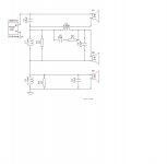
A 3 way series crossover
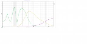
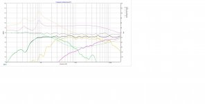
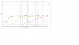
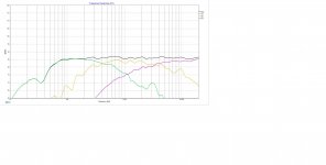
Woofer to midrange crossover point is around 370 hz. Midrange to Tweeter crossover point is around 6100 hz. Adding the crossover file below with some pictures. Light green - woofer response, yellow - midrange and purple - tweeter. No baffle step correction as measurements were already taken while drivers mounted on baffles ( links provided in driver listing area).
I do not have simulation skill or softwares installed and not much understanding about step response, impulse response or group delay. I did not extract minimum phase to design the crossover and did not consider polar response.
I understand the design is not full-proof and might not produce optimal results. Still i am thrilled to go ahead and learn and enjoy the building process. I call for help to everyone here. Every suggestion, advice and opinion will be valuable for me. Thanks in advance.
Regards
Ujjwal
........
Hope everyone is doing okay in this challenging time. I am a doctor from India and trying to design and build a 3-way speaker for the first time. This forum has always been tremendously helpful regarding any doubt associated with audio.
I know speaker designing is very much complicated and needs knowledge and skill. Without proper measurements and knowledge it is quite impossible to pull out a good design. I chose the drivers which are available here in India and easy to work with according to my understanding. I do not have any measuring device at present (not available locally or online in India). I used measurements from other established designs which used the same drivers I am going to use in my design (not the perfect way to do it). So it is flawed, but I accept it and am ready to go ahead and make necessary changes if I can.
Drivers
1. Peerless HDS woofer 830869 for woofer duty. Link: Peerless by Tymphany 830869 8" Nomex Cone HDS Woofer
measurements i used for this driver: Peerless 830869 HDS Nomex 8″ Woofer – AmpsLab
2. Tang Band W5- 2143 for midrange. Link Tang Band W5-2143 5" Paper Cone Full Range Driver 8 Ohm
measurements i used:
COGのブログ:TangBand W5-2143 36L ZWBR
3. Peerless by Tymphany XT25TG30-04 1" Dual Ring Radiator Tweeter for highs. Link Peerless by Tymphany XT25TG30-04 1" Dual Ring Radiator Tweeter
I manufacturer measurements available in parts-express page.
Cabinet Design:
The woofer will be housed in a MLTL cabinet. Internal dimensions are 34 inch high, 8.3 inch wide and 11.5 inch deep.
Woofer centre is 6.75 inch below the internal top.
The port is 5.5 inch long with 3 inch diameter and placed 3.5 inch above internal bottom. [ Thanks to P. Kittinger who helped me regarding this]
The midrange driver will be housed in back open tunnel above woofer cabinet with internal dimensions of 8.3 inch width x 6.3 inch height x 11.5 inch depth. This tunnel will be lined by 1 inch thick foam. The back of the tunnel has a circular opening of 5.5 inch diameter which will be covered and attenuated by 3 inch thick foam pad.
The tweeter will be housed above the midrange cabinet.
So eventually the baffle will be 9.8 inch wide[ baffle step is around 465 hz], 47 inch tall.
Crossover
Designed by Xsim. I used FPgraph tracer to trace Frequency responses. The links for the source of frequency response for each driver are mentioned earlier where i enlisted the drivers. Woofer response curve was originally measured in 10.5 inch baffle which is almost 0.7 inch wider than my design ( my baffle will be 9.8 inch). Hence there may be significant difference in woofer response. Same may be true for midrange. I need valuable opinion(s) and suggestion(s) from you guys. I also used impedance response of the woofer derived from the modeling of the woofer cabinet( done with the help of M.J. King software).
A 3 way series crossover
Woofer to midrange crossover point is around 370 hz. Midrange to Tweeter crossover point is around 6100 hz. Adding the crossover file below with some pictures. Light green - woofer response, yellow - midrange and purple - tweeter. No baffle step correction as measurements were already taken while drivers mounted on baffles ( links provided in driver listing area).
I do not have simulation skill or softwares installed and not much understanding about step response, impulse response or group delay. I did not extract minimum phase to design the crossover and did not consider polar response.
I understand the design is not full-proof and might not produce optimal results. Still i am thrilled to go ahead and learn and enjoy the building process. I call for help to everyone here. Every suggestion, advice and opinion will be valuable for me. Thanks in advance.
Regards
Ujjwal
........
Attachments
-
P+TB+P.dxo126.5 KB · Views: 72
-
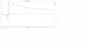 Crossover Step Response.jpg91.5 KB · Views: 104
 -
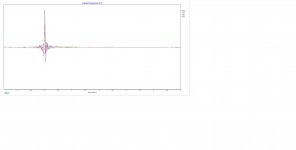 Crossover Impuse response.jpg76.1 KB · Views: 103
 -
 Crossover 6 power dissipation.jpg201.9 KB · Views: 89
 -
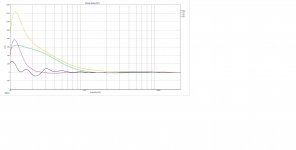 Crossover 5 group delay.jpg162.1 KB · Views: 483
 -
 Crossover 4 components.jpg39.5 KB · Views: 490
 -
 Crossover 3 with phase.jpg219.6 KB · Views: 518
 -
 Crossover 2.jpg199.5 KB · Views: 481
 -
 Crossover 1.jpg151.3 KB · Views: 481
Last edited:
Hopefully that is the same as the speakers from which you borrowed the plots.baffle step is around 465 hz
No problem for now.not much understanding about step response, impulse response or group delay.
It is not possible to extract minumum phase from this data, but Xsim will derive something based on the response only. What do you know about the plots you have?I did not extract minimum phase
This can come after you have a mic.and did not consider polar response.
I don't know where to start, because I see several problems in what you did. So my comments are in no particular order.
1) Driver measurement
It seems you used a mix of published and measured data for FR. The best way to collect a FR is to directly measure the drivers in the box/baffle you will use. If you can't measure, the best approach is to trace the manufacturer data and simulate the baffle effect. If you omit this step your driver FR is unusable to create a crossover because it is wrong to start with. OTOH if you use someone else FR, as it is the case with the woofer, you should trust what you are using, and I'm a bit suspicious on the woofer FR, simply because I don't see the baffle step effect, so for a dose of reality I'd trace the mfg FR also for the woofer and then simulate the baffle effect.
FR data should include also phase, and I see your data don't have it. FR without real phase data are useless and will lead to a bad crossover. This is where the measurement is essential, as true phase can only be collected through a measure, deriving minimum phase from a simulated FR is only an approximation but at least you should do that.
2) Impedance
Don't use TS derived impedance, as TS parameters won't fully predict the whole impedance curve. It is way better to trace mfg graphs and derive phase.
3) Choice of drivers
I have nothing to say about the chosen woofer and tweeter, as they are perfectly valid drivers for the scope. I'm a bit worried about the mid, as TB don't offer off-axis data, so you can't really know where to cross it over (more on this later). Even the on-axis FR published is, as always with TB, difficult to work with as the scale is very compressed and the graph is smoothed. Moreover a real full range driver is an exercise in compromise, I'm a bit worried about the wrinkles in the impedance that will have for sure some effects. Frankly I'd use a slightly smaller driver (4-4.5") for which there is a published off-axis FR, a real mid or a mid-bass.
4) Crossover points and slopes
Crossover point between woofer and mid can be around the baffle step frequency, as this will ease the crossover design, so in this respect you are on the right path. For a smooth transition in directivity the crossover point between mid and tweeter should be chosen where the mid starts to beam (let say where the 30 deg off axis FR is -3dB from the on-axis FR), you don't have this data, but clearly 6KHz is way to high for a 5.5" driver. With a 4-4.5" mid you can easily choose a 3 KHz crossover point.
In general electrical slopes doesn't really mean anything. What really matter are acoustical slopes. On a flat baffle you can easily use LR2 slopes between woofer and mid and LR4 slopes between mid and tweeter.
One last thing about the crossover simulation is to have valid data about path difference between the various drivers. This has to be calculated, and the tricky part for the mid-tweeter crossover is to determine where the sound is emitted in the case of the mid, as it is beyond the baffle. This can easily be measured, but you have to insert at least an approximate value in the crossover simulation tool. In a 3-way I did I calculated a 0.75" path difference between a 125mm mid and a tweeter. The value you enter here is critical for a good crossover simulation at the frequencies involved.
5) Cabinet
It seems you have had help with the cab enclosure, so I won't comment on this. However simulating the enclosure for the mid is a bit tricky and I'm not entirely sure it won't interfere with the crossover point you're using.
As a general remark, starting designing speakers with a 3-way is pretty foolish, because a 3 way is much more difficult than a 2 way, the chance to have it done right at the first try approaches zero. Without measurement capabilities it is really difficult to understand by ear the problems and how to resolve them, I won't say it is impossible but...
Ralf
Hi Ujju3doc,
Well you got some advice there 🙂
It is sensible advice so difficult to counter. But lets see if we can go forward.
In these difficult times, more so being a doctor you may need something else to take your mind away from work.
You have obviously spent some time researching and learning some of the fundamental stuff and have provided details of proposed cabinets and frequency response plus crossover based on copied curves from manufacturers data and other peoples designs. There is a lot of stuff there already. The speakers chosen look like thye will work well.
have you already purchased the drivers or started to build the cabinets?
If you have started the build, whilst you tune this design I would be tempted to use a conventional crossover so that you can tune each individual driver stage in isolation without effecting the other. Just a thought.
The crossover frequencies are in sensible places, so you certainly will have sound. Some people like use the baffle step frequency to Xover bass to mid, but you are pretty close an i think the Tang band can handle it.
Because of the baffle driver spacings between the bass mid, and treble and how far they are set back relative to each other the relative positions are all going to effect the overall frequency response.
The acoustic centres of drivers are somewhere between the outer edge of the cone and the voice coil, which can be tricky to get perfect without measurements, but these can be initially estimated.
Within these constraints your design will definitely make sound when you initially wire it up to an amplifier, but after a while you may realise somethings is less than ideal, all simulations will need tweaking that's a given fact.
Before connecting to an amplifier it might be worthwhile checking the basic resistance with an ohmmeter just to guarantee it isn't a very low impedance or short which could damage the amp. Which would not be a good start.
Too much or too little treble is an obvious one but you can adjust that by resistive padding.... usually.
Failing that with some tweeter Xover capacitor changes may be needed. Do not forget if aiming for a highish mid to tweeter Xover you need to keep these as close together as possible, so a small faceplate tweeter is usually used here to keep the separation distance small. But at 6Khz you wont be able to do this so I wouldn't worry about that at all.
As the mid and tweeter housing sits on top of the MLTL cabinet you should make these free moving then you can make slight adjustments if necessary forward and back to adjust response
As to some basic measurement it may be worthwhile looking for some smart phone based FFT audio analysers. Dependent on you phones microphone you may get some sensible readings. Others may chip in with advice on their suitability. Others have mentioned that you can use your laptop PC inbuild microphone to interface with the likes of REW and ARTA software.
Alternatively as others have suggested a kit, maybe look at building a SB acoustics kit. I think some people there in India have mentioned SB loudspeakers being available.
Finally may I suggest that you have a look at this FINE X video it it is very educational 5 mins re crossover tuning and tweaking, you may just learn something useful as in the latter part of the video it discusses three ways driver positions and phasing.
Videos | Watch videos of all products right here.
Good luck and stay safe in these difficult times.
Last edited:
I think you should just build it, but be prepared to tweak... Any reason for the series xover? A brave choice for a first build, but sims OK. Parallel is a bit easier when tweaking.
re:'3 way is much more difficult than a 2 way' - I don't agree with this, well selected drivers in a 3 way aren't being pushed to their limits as much as in a comparable 2 way, so crossovers will be closer to textbook. (Although 'well selected' does assume some prior knowledge). However, this probably isn't the thread to debate this...
re:'3 way is much more difficult than a 2 way' - I don't agree with this, well selected drivers in a 3 way aren't being pushed to their limits as much as in a comparable 2 way, so crossovers will be closer to textbook. (Although 'well selected' does assume some prior knowledge). However, this probably isn't the thread to debate this...
Hopefully that is the same as the speakers from which you borrowed the plots.No problem for now.It is not possible to extract minumum phase from this data, but Xsim will derive something based on the response only. What do you know about the plots you have?This can come after you have a mic.
Thanks I appreciate your prompt response
I don't know where to start, because I see several problems in what you did. So my comments are in no particular order.
1) Driver measurement
It seems you used a mix of published and measured data for FR. The best way to collect a FR is to directly measure the drivers in the box/baffle you will use. If you can't measure, the best approach is to trace the manufacturer data and simulate the baffle effect. If you omit this step your driver FR is unusable to create a crossover because it is wrong to start with. OTOH if you use someone else FR, as it is the case with the woofer, you should trust what you are using, and I'm a bit suspicious on the woofer FR, simply because I don't see the baffle step effect, so for a dose of reality I'd trace the mfg FR also for the woofer and then simulate the baffle effect.
FR data should include also phase, and I see your data don't have it. FR without real phase data are useless and will lead to a bad crossover. This is where the measurement is essential, as true phase can only be collected through a measure, deriving minimum phase from a simulated FR is only an approximation but at least you should do that.
2) Impedance
Don't use TS derived impedance, as TS parameters won't fully predict the whole impedance curve. It is way better to trace mfg graphs and derive phase.
3) Choice of drivers
I have nothing to say about the chosen woofer and tweeter, as they are perfectly valid drivers for the scope. I'm a bit worried about the mid, as TB don't offer off-axis data, so you can't really know where to cross it over (more on this later). Even the on-axis FR published is, as always with TB, difficult to work with as the scale is very compressed and the graph is smoothed. Moreover a real full range driver is an exercise in compromise, I'm a bit worried about the wrinkles in the impedance that will have for sure some effects. Frankly I'd use a slightly smaller driver (4-4.5") for which there is a published off-axis FR, a real mid or a mid-bass.
4) Crossover points and slopes
Crossover point between woofer and mid can be around the baffle step frequency, as this will ease the crossover design, so in this respect you are on the right path. For a smooth transition in directivity the crossover point between mid and tweeter should be chosen where the mid starts to beam (let say where the 30 deg off axis FR is -3dB from the on-axis FR), you don't have this data, but clearly 6KHz is way to high for a 5.5" driver. With a 4-4.5" mid you can easily choose a 3 KHz crossover point.
In general electrical slopes doesn't really mean anything. What really matter are acoustical slopes. On a flat baffle you can easily use LR2 slopes between woofer and mid and LR4 slopes between mid and tweeter.
One last thing about the crossover simulation is to have valid data about path difference between the various drivers. This has to be calculated, and the tricky part for the mid-tweeter crossover is to determine where the sound is emitted in the case of the mid, as it is beyond the baffle. This can easily be measured, but you have to insert at least an approximate value in the crossover simulation tool. In a 3-way I did I calculated a 0.75" path difference between a 125mm mid and a tweeter. The value you enter here is critical for a good crossover simulation at the frequencies involved.
5) Cabinet
It seems you have had help with the cab enclosure, so I won't comment on this. However simulating the enclosure for the mid is a bit tricky and I'm not entirely sure it won't interfere with the crossover point you're using.
As a general remark, starting designing speakers with a 3-way is pretty foolish, because a 3 way is much more difficult than a 2 way, the chance to have it done right at the first try approaches zero. Without measurement capabilities it is really difficult to understand by ear the problems and how to resolve them, I won't say it is impossible but...
Ralf
Your points are valid and i agree with them mostly. Thanks for pointing out the flaws.
Hi Ujju3doc,
Well you got some advice there 🙂
It is sensible advice so difficult to counter. But lets see if we can go forward.
In these difficult times, more so being a doctor you may need something else to take your mind away from work.
You have obviously spent some time researching and learning some of the fundamental stuff and have provided details of proposed cabinets and frequency response plus crossover based on copied curves from manufacturers data and other peoples designs. There is a lot of stuff there already. The speakers chosen look like thye will work well.
have you already purchased the drivers or started to build the cabinets?
If you have started the build, whilst you tune this design I would be tempted to use a conventional crossover so that you can tune each individual driver stage in isolation without effecting the other. Just a thought.
The crossover frequencies are in sensible places, so you certainly will have sound. Some people like use the baffle step frequency to Xover bass to mid, but you are pretty close an i think the Tang band can handle it.
Because of the baffle driver spacings between the bass mid, and treble and how far they are set back relative to each other the relative positions are all going to effect the overall frequency response.
The acoustic centres of drivers are somewhere between the outer edge of the cone and the voice coil, which can be tricky to get perfect without measurements, but these can be initially estimated.
Within these constraints your design will definitely make sound when you initially wire it up to an amplifier, but after a while you may realise somethings is less than ideal, all simulations will need tweaking that's a given fact.
Before connecting to an amplifier it might be worthwhile checking the basic resistance with an ohmmeter just to guarantee it isn't a very low impedance or short which could damage the amp. Which would not be a good start.
Too much or too little treble is an obvious one but you can adjust that by resistive padding.... usually.
Failing that with some tweeter Xover capacitor changes may be needed. Do not forget if aiming for a highish mid to tweeter Xover you need to keep these as close together as possible, so a small faceplate tweeter is usually used here to keep the separation distance small. But at 6Khz you wont be able to do this so I wouldn't worry about that at all.
As the mid and tweeter housing sits on top of the MLTL cabinet you should make these free moving then you can make slight adjustments if necessary forward and back to adjust response
As to some basic measurement it may be worthwhile looking for some smart phone based FFT audio analysers. Dependent on you phones microphone you may get some sensible readings. Others may chip in with advice on their suitability. Others have mentioned that you can use your laptop PC inbuild microphone to interface with the likes of REW and ARTA software.
Alternatively as others have suggested a kit, maybe look at building a SB acoustics kit. I think some people there in India have mentioned SB loudspeakers being available.
Finally may I suggest that you have a look at this FINE X video it it is very educational 5 mins re crossover tuning and tweaking, you may just learn something useful as in the latter part of the video it discusses three ways driver positions and phasing.
Videos | Watch videos of all products right here.
Good luck and stay safe in these difficult times.
Thanks for your reply. Did not buy the drivers yet. I realise now i should buy a Mic first and learn to measure properly. i should also learn simulation. That way is to be followed if I want to design and build something properly.
I think you should just build it, but be prepared to tweak... Any reason for the series xover? A brave choice for a first build, but sims OK. Parallel is a bit easier when tweaking.
re:'3 way is much more difficult than a 2 way' - I don't agree with this, well selected drivers in a 3 way aren't being pushed to their limits as much as in a comparable 2 way, so crossovers will be closer to textbook. (Although 'well selected' does assume some prior knowledge). However, this probably isn't the thread to debate this...
I wanted to use 1st order xover for woofer to mids transition which was easier and more effective using series crossover. You are right that a parallel Xover will be easier to tweak. Thanks
"easier and more effective using series crossover" - Rod Elliot doesn't agree: Series vs. Parallel Crossover Networks
True.. I think the advantage of the series network like the one Rod shows, is what it is able to achieve using the lowest number of components.
Since both drivers are in parallel there is some inadvertent impedance compensation, and you get more than first order filters for just two components... If you can choose the right ones.
There are some tricks to getting them right though..
Since both drivers are in parallel there is some inadvertent impedance compensation, and you get more than first order filters for just two components... If you can choose the right ones.
There are some tricks to getting them right though..

@ujju3doc, please refrain from quoting whole posts unless you plan to reply point by point.
It makes things very difficult for us to read, with one very long quote followed by a one-line reply.
As the editor notes, please trim quotes to whatever specific point you wish to reply to.
Thanks for understanding.
"easier and more effective using series crossover" - Rod Elliot doesn't agree: Series vs. Parallel Crossover Networks
If i remember correctly Rod said there may be advantage(may be little) of series crossover if considered in case of first order over parallel. Correct me if i am wrong.
duly noted, will do henceforth. Thanks.
@ujju3doc, please refrain from quoting whole posts unless you plan to reply point by point.
It makes things very difficult for us to read, with one very long quote followed by a one-line reply.
As the editor notes, please trim quotes to whatever specific point you wish to reply to.
Thanks for understanding.
I Am not good at simulation. MY computer has Office 2016. There are some issues for which i cannot use J. Bagby's Response modeller. Can someone lend me a helping hand and do a baffle step response of the woofer Peerless 830869 from the manufacturer's published curves. I will really appreciate the kind gesture if someone does.
The above link to Rod Elliot article makes for an interesting read but it does not seem to be 100% conclusive as to which is ultimately better.
Once happy with the design it would be very interesting to swap to the alternative style of crossover. I must try it at some point this year. I would certainly like to understand sound versus cost considerations. Maybe I could I save money with serial Xovers in the future. Big L's and C's are expensive. maybe it is time to start making my own.
Back on topic.
For ujju3doc as PeteMcK suggests, build it and tweak it. It should sound passable and you could live with its sound for years after some basic tweaking of tweeter level etc.
Imagine that you have been happily listening to it for many years and then one day somebody close to you buys you a measuring system. Your first measurement will be pants, it will take time to understand the measuring system, its shortcomings and what it can actually tell you. Once you understand the measuring system you may find that you have the phase wrong on a driver giving you a x dB suck out less than perfect levels. Consequently you will re do the crossover, possibly flip the driver polarity to see if that effects the null etc. etc.
With the measuring system and some experimentation you will make a better measuring loudspeaker, will you like it as much as the original possibly?
I hope this turns out to be fun, are you going to make the cabinets yourself?
What is it like for components in Kolcatta, are inductors easily sourced, what type of film capacitors can you get from supplier or markets. I know you can order from the likes of Farnell and RS etc.
Here in kolkata i can get Dayton caps also Jantzen. Same goes for coils.
I posted the new tweaked crossover. Now I want to ask you guys who are far more experienced than me whether it will be worthwhile to go ahead. Whether it will will sound good or it will be a disaster.
If you guys think.. Chances are more on the side of disaster.. Then I clearly want to save my money... Hahahaha.
So please come forward and let me know your opinions. I will update the cabinet plans and precise driver centre-to-centre distances.
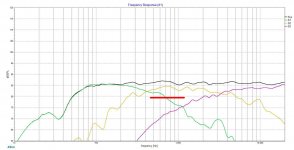
Actually I have taken the woofer spl curve from Falcon -III speaker which was designed by Amplab. Peerless 830869 has around 90 db sensitivity. The measurements I followed was giving around 85-86 db. In Falcon-III the same woofer was mounted in a 10.5 inch wide baffle and measured. My build will have a 9.8 inch wide baffle. So I guess baffle step loss is already taken care of. Here is the link of the page
FALCON-III Baffleless Concept Speaker – AmpsLab
FALCON-III Baffleless Concept Speaker – AmpsLab
- Home
- Loudspeakers
- Multi-Way
- First 3-way speaker and crossover